Anti-leakage device and method for slurry in desulfurization and denitrification process

A desulfurization, denitrification, and leakage prevention technology, applied in separation methods, chemical instruments and methods, and dispersed particle separation, etc., can solve problems such as slurry leakage, detachment of demister bolts, and component aging, so as to avoid corrosion of pipelines and impurities. Residue, reduce the effect of slurry leakage

Active Publication Date: 2022-03-25
MAANSHAN SHUNDA ENVIRONMENTAL PROTECTION EQUIP
View PDF0 Cites 0 Cited by
  • Summary
  • Abstract
  • Description
  • Claims
  • Application Information

AI Technical Summary

Problems solved by technology

First, the demister of the desulfurization and denitrification equipment in the brick factory has been used for a long time, and many components inside the equipment are aging; second, part of the high-temperature flue gas has not been sprayed for cooling, and directly contacts the demister. The surface of the equipment is scalded and there is slurry leakage; third, when the demister is blocked, the pressure of the flue gas will gradually increase, and eventually the gap of the demister will be opened to cause slurry leakage; fourth , The bolts used to fix the demister are not fastened tightly and fall off, causing the demister to crack
[0003] It can be said that the slurry leakage of desulfurization and denitrification equipment is basically caused by the accumulation of too many impurities in the demister, but if the demister is maintained, the existing method is to disassemble the equipment for replacement, but this method is time-consuming and laborious. Therefore, a device that can automatically clean the demister is needed, so as to indirectly avoid the occurrence of slurry leakage

Method used


Image

  • Anti-leakage device and method for slurry in desulfurization and denitrification process
  • Anti-leakage device and method for slurry in desulfurization and denitrification process
  • Anti-leakage device and method for slurry in desulfurization and denitrification process

Examples


Embodiment Construction

[0031] The technical solutions in the embodiments of the present invention will be clearly and completely described below with reference to the accompanying drawings in the embodiments of the present invention. Obviously, the described embodiments are only a part of the embodiments of the present invention, but not all of the embodiments. Based on the embodiments of the present invention, all other embodiments obtained by those of ordinary skill in the art without creative efforts shall fall within the protection scope of the present invention.

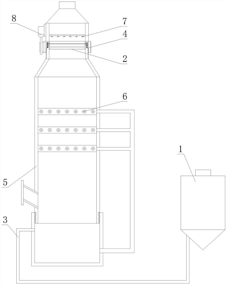
[0032] see figure 1 , a desulfurization and denitration process slurry anti-leakage device, comprising an absorbent bin 1, a circulation box 3 and an absorption tower 5, the circulation box 3 is installed at the bottom end of the absorption tower 5, the top of the circulation box 3 is installed with threads, and the circulation box 3 passes through The absorption tower 5 is movably connected to the absorption tower 5 by means of screw...


PUM


Abstract

The invention discloses a slurry leakage prevention device and method for desulfurization and denitrification process, wherein the circulation box can be disassembled freely to facilitate subsequent maintenance, and the clean water sprayed by the clear water spray head is sprayed on the impurity removal round frame, the brush and the removal The fog fan is placed on the three, so as to ensure the residue of impurities, the demister can absorb the acid-containing impurity water droplets in the rising flue gas to a large extent, so as to avoid the acid mist water droplets from corroding the pipeline, avoiding the occurrence of slurry leakage, and the device is running When the brush extends into the gap between two adjacent defogging fans, the brush moves up and down to clean the outer wall of the defogging fan to avoid residues of impurities. Moving up and down, the sealing plate is used for sealing to prevent the slurry in the absorption tower from overflowing from the vertical groove on the side wall of the absorption tower, that is, the brush moves up and down to clean the demister. After the demister is cleaned, the leakage can be greatly reduced. The occurrence of slurry can also effectively prevent the corrosion of pipelines by water droplets containing acid mist.

Description

technical field [0001] The invention relates to desulfurization and denitrification equipment, in particular to a desulfurization and denitration process slurry anti-leakage device and method. Background technique [0002] During the operation of desulfurization and denitrification equipment, many problems are often encountered. For example, when the desulfurization and denitrification equipment is operating, the slurry leakage occurs. The occurrence of the slurry leakage mainly includes the following four aspects. First, the demister of the desulfurization and denitrification equipment in the brick factory has been used for a long time, and many components inside the equipment have aged; Cause the surface of the equipment to be scalded and leak slurry; third, when the mist eliminator is blocked, the pressure of the flue gas will gradually expand, and eventually the gap of the mist eliminator will be flushed out, resulting in leakage of the slurry; fourth , the bolts used ...

Claims


Application Information

Patent Timeline
Patent Type & Authority Patents(China)
IPC IPC(8): B01D53/18B01D49/00
CPCB01D53/18B01D53/1456B01D53/185B01D49/00
Inventor 王春保林超
Owner MAANSHAN SHUNDA ENVIRONMENTAL PROTECTION EQUIP
Why Eureka
Try Eureka