Supercharge Your Innovation With Domain-Expert AI Agents!

Parallel split type worm and gear sealing structure with independent oil inlet holes

A technology of worm gear and sealing structure, which is applied in the direction of engine sealing, gear transmission, belt/chain/gear, etc., can solve the problems of inability to control temperature rise, accumulative pitch error, pitch error, etc., and improve the friction state. , the effect of improving the carrying capacity

Inactive Publication Date: 2014-06-04
刘继清
View PDF3 Cites 0 Cited by
  • Summary
  • Abstract
  • Description
  • Claims
  • Application Information

AI Technical Summary

Problems solved by technology

However, ZL200710035077.2 does not involve the design of the oil supply hole, and it cannot control the temperature rise of each meshing section of the worm gear and worm pair from meshing in to meshing out, and cannot control the thermal expansion of the worm and the corresponding section of the worm wheel, causing working conditions The pitch error and cumulative pitch error of the lower teeth make it difficult to effectively control the meshing state of the large modulus worm gear

Method used


Image

  • Parallel split type worm and gear sealing structure with independent oil inlet holes
  • Parallel split type worm and gear sealing structure with independent oil inlet holes
  • Parallel split type worm and gear sealing structure with independent oil inlet holes

Examples


Embodiment Construction

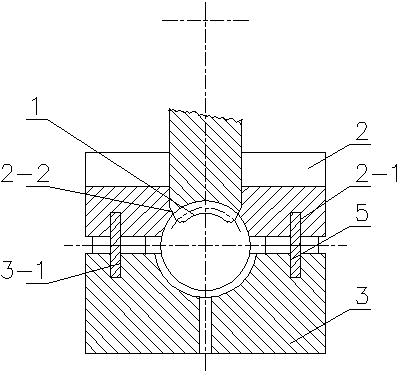
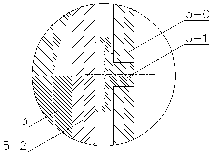
[0015] Below in conjunction with all accompanying drawings the present invention will be further described, and preferred embodiment of the present invention is: see appended figure 1 To attach Image 6 , the sealing structure described in this embodiment is composed of a worm wheel flange seal, a worm axial seal, a worm end face seal, and a worm radial seal, wherein the worm axial seal is formed by combining the middle seal block 2 and the outer seal block 3, The bonding surface of the middle seal block 2 and the outer seal block 3 is parallel to or slightly inclined to the axis of the worm gear, and the inclination angle is within 30 degrees. Both sides of the middle sealing block 2 and the outer sealing block 3 are respectively provided with the middle sealing groove 2-1 and the outer sealing groove 3-1, and the sealing strip 6 is embedded in the middle sealing groove 2-1 and the outer sealing groove 3-1 to form a seal A plurality of independent oil inlet holes 4 are distr...


PUM


Abstract

The invention provides a parallel split type worm and gear sealing structure with independent oil inlet holes. The sealing structure for the worm and gear meshing region includes a gear rim seal, a worm axial seal, a worm end face seal and a worm radial seal, and is used for controlling oil leakage and guaranteeing pressure of lubricating oil at the meshing region so as to reduce contact between the meshing surfaces, reduce the friction coefficient and improve transmission efficiency. A plurality of independent oil inlet holes are distributed on a seal block of the worm axial seal along the worm axis. Cooling strength and temperature rise of various sections from the meshing-in end to the meshing-out end can be controlled by controlling position, temperature and flow of lubricating oil entering the meshing region, and accordingly heat expansion difference between a gear and the worm, among teeth of the gear and among teeth of the worm can be controlled and loads of different meshing teeth are equalized.

Description

technical field [0001] The invention relates to the technical field of worm gears, in particular to a worm gear sealing structure with parallel split independent oil inlet holes. Background technique [0002] The worm gear is a well-known basic transmission mechanism. The usual worm gear has the advantages of large speed ratio, simple structure or compact structure. The relative sliding speed between the meshing surfaces of the worm is fast, and the lubricating oil driven by the rotation of the worm has a strong centrifugal effect, which makes the condition for the formation of the oil film in the meshing area poor, and the oil churning loss of the worm causes serious wear and tear of the worm transmission, high heat generation and transmission Low efficiency and other shortcomings. In the existing transmission technology of worm gears, except for ZL200710035077.2 which proposes the concept of sealing the meshing area, none of the others have sealed the meshing area. Howev...

Claims


Application Information

Patent Timeline
Patent Type & Authority Patents(China)
IPC IPC(8): F16H1/16F16H57/029F16J15/00
Inventor 刘继清
Owner 刘继清
Features
  • R&D
  • Intellectual Property
  • Life Sciences
  • Materials
  • Tech Scout
  • Unparalleled Data Quality
  • Higher Quality Content
  • 60% Fewer Hallucinations
Learn More