
Transition ring structure for rotating joint

A technology of rotary joints and transition rings, which is applied in the direction of engine seals, engine components, mechanical equipment, etc., and can solve problems such as low tensile strength

Inactive Publication Date: 2012-07-11
DALIAN HUAYANG SEALS
View PDF3 Cites 0 Cited by
  • Summary
  • Abstract
  • Description
  • Claims
  • Application Information

AI Technical Summary

Problems solved by technology

[0002] At present, most of the rotary joints with mechanical seal structure on the market use spherical friction pair structures with more degrees of freedom to resist vibration and swing. In order to adapt to the vibration and swing of field equipment, the transition ring adopts a spherical surface on one side and a plane on the other side. Design structure, this structure can ensure that the transition ring can float and compensate when the shaft is deflected, and ensure the sealing effect of the rotary joint. Since the transition ring bears axial pressure and radial tension at the same time during work, the transition ring needs to be installed The metal insert ring is used to increase the tensile strength of the transition ring. This structure has some problems: 1. Since the transition ring is made of graphite material with good wear resistance and self-lubricating properties, the tensile strength of the transition ring is low, so it must be inlaid Install a metal mounting ring with sufficient clamping force; 2. The transition ring participates in two friction pairs at the same time, so sufficient working height should be reserved on both sides of the mounting ring to ensure the normal operation of the rotary joint within a unit time. The transition ring can only be scrapped when one side of the ring is heavily worn

Method used


Image

  • Transition ring structure for rotating joint
  • Transition ring structure for rotating joint

Examples


Embodiment Construction

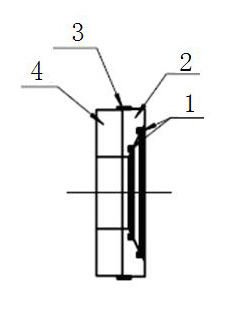
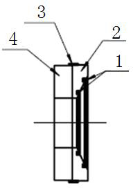
[0008] Such as figure 1 As shown, the transition ring structure of the rotary joint includes a sealing ring 1, a spherical body 2, an inlay ring 3 and a graphite ring 4, the sealing ring 1 is installed on the spherical body 2, and the spherical body 2 is connected to the graphite ring 4 through the inlay ring 3 , the present invention adopts a transition ring inlaid structure, and the flat sealing parts of the sealing surfaces on both sides are made of graphite material; the spherical sealing part and the metal are used as the matrix, filled with polytetrafluoroethylene as the sealing ring, and the outer side of the transition ring is sealed with a metal inlaid ring. The components are snapped together to achieve the integrity of the transition ring.


PUM


Abstract

The invention discloses a transition ring structure for a rotating joint. The transition ring structure comprises a seal ring (1), a spherical body (2), an inserting ring (3) and a graphite ring (4), wherein the seal ring (1) is mounted on the spherical body (2); the spherical body (2) is connected with the graphite ring (4) through the inserting ring (3); for the transition ring structure, the graphite ring only suffers from pressure, but does not suffer from radial tension, a protective inserting ring does not need to be embedded, a polytetrafluorethylene seal ring with good plasticity is used for sealing the spherical surface side of the transition ring, so that the processing precision on the surface of the metal sphere is not required to be too high; the graphite material with high price is only arranged on the plane friction surface side of the transition ring, and only the graphite ring needs to be replaced after the graphite material suffers from severe abrasion, so that the maintenance is facilitated, and great amount of cost can be saved; an anti-rotation structure is additionally arranged on the spherical body, so that a spherical friction pair only bears the sealing effect of the rotating joint, but does not participate in sealing between relative rotation between a rotating shaft and a shell, so that the abrasion degree of the spherical sealing parts can be effectively reduced.

Description

technical field [0001] The invention relates to the technical field of mechanical seals, in particular to a rotary joint transition ring structure. Background technique [0002] At present, most of the rotary joints with mechanical seal structure on the market use spherical friction pair structures with more degrees of freedom to resist vibration and swing. In order to adapt to the vibration and swing of field equipment, the transition ring adopts a spherical surface on one side and a plane on the other side. Design structure, this structure can ensure that the transition ring can float and compensate when the shaft is deflected, and ensure the sealing effect of the rotary joint. Since the transition ring bears axial pressure and radial tension at the same time during work, the transition ring needs to be installed The metal insert ring is used to increase the tensile strength of the transition ring. This structure has some problems: 1. Since the transition ring is made of g...

Claims


Application Information

Patent Timeline
IPC IPC(8): F16J15/30
Inventor 年立胜
Owner DALIAN HUAYANG SEALS
Learn More