Fixing device for disc drive

A technology of disk drive and fixing device, which is applied in the direction of digital processing power distribution, etc., and can solve problems such as unstable installation

Inactive Publication Date: 2012-07-11
SCIENBIZIP CONSULTINGSHENZHENCO
View PDF4 Cites 1 Cited by
  • Summary
  • Abstract
  • Description
  • Claims
  • Application Information

AI Technical Summary

Problems solved by technology

However, there is inevitably a fit gap between these fixed structures and the computer case, resulting in unstable installation

Method used


Image

  • Fixing device for disc drive
  • Fixing device for disc drive
  • Fixing device for disc drive

Examples


Embodiment Construction

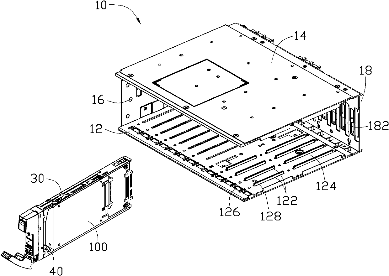
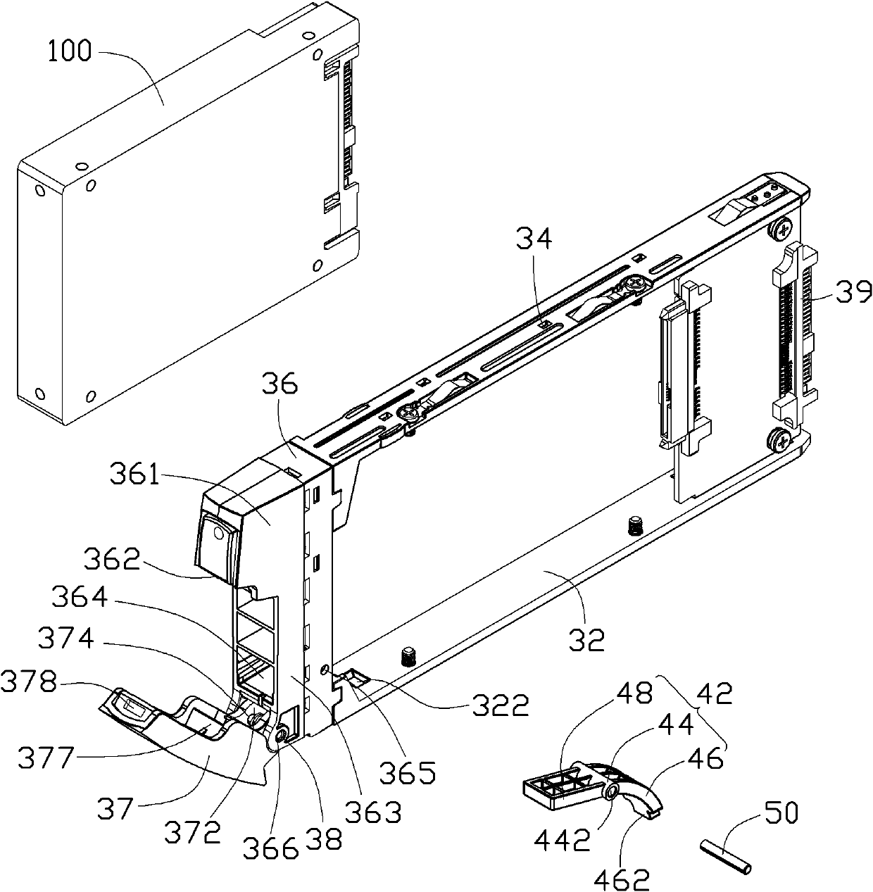
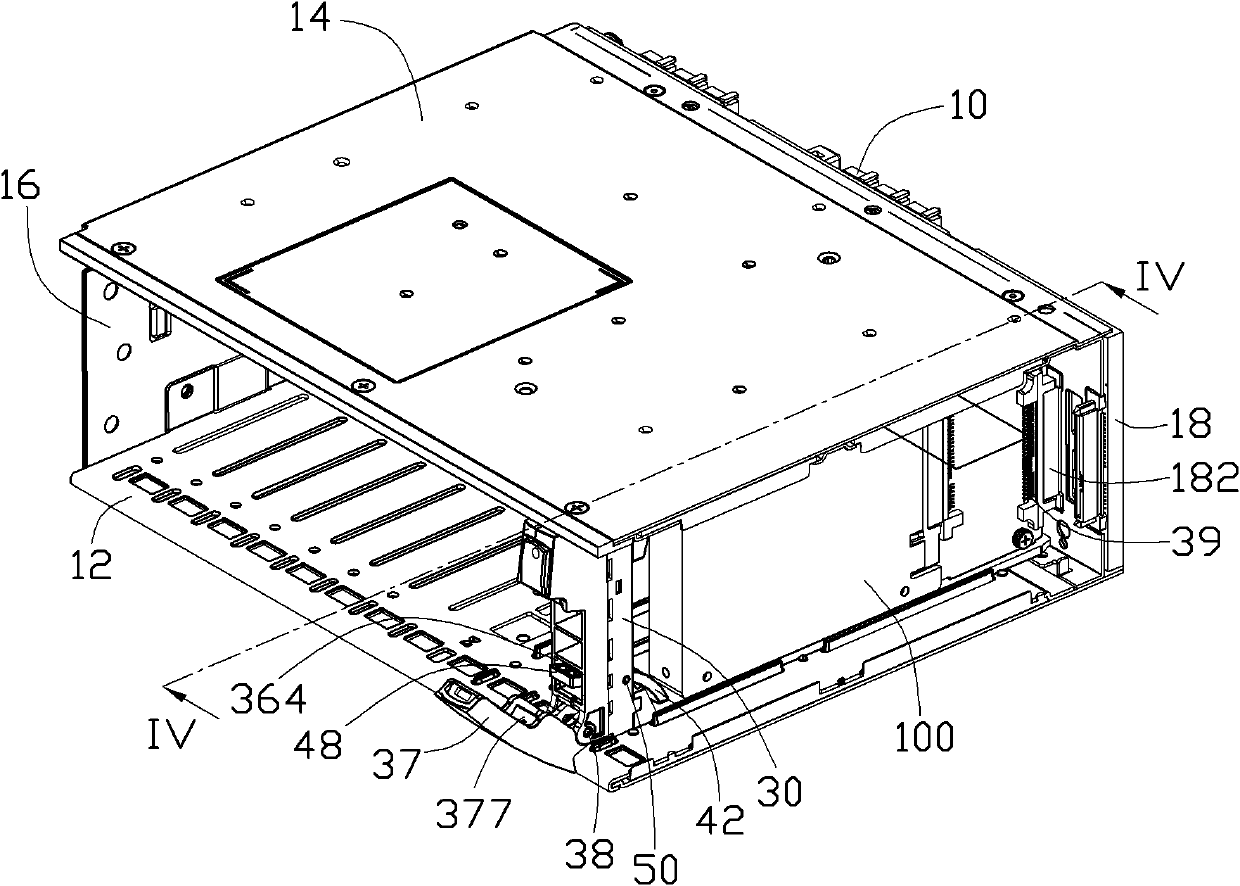
[0049] Please refer to figure 1 A preferred embodiment of the disk drive fixing device of the present invention includes a casing 10, a fixing frame 30 for fixing the disk drive 100 and can be accommodated in the casing 10, and a pressing mechanism pivotally mounted on the fixing frame 30 40.

[0050] The housing 10 includes a first side wall 12 and a second side wall 14 oppositely disposed. First ends of the first sidewall 12 and the second sidewall 14 form an installation opening 16 . A vertical wall 18 is vertically disposed on the second ends of the first side wall 12 and the second side wall 14 . The first side wall 12 protrudes from two parallel elongated ribs 122 , and a slideway 124 is formed between the two ribs 122 . The first side wall 12 defines a fastening hole 126 facing the slideway 124 at a position close to the installation opening 16 , and a shock absorbing pad 128 is disposed in the slideway 124 . The vertical wall 18 is provided with a first connector 1...


PUM


Abstract

The invention relates to a fixing device for a disc drive. The fixing device comprises a shell, a fixing frame and a fastening piece, wherein the fixing frame is accommodated in the shell and is used for fixing the disc drive; the fastening piece is mounted on the fixing frame in a pivoted manner; a holding fixing hole is formed in the shell; a locking handle is pivoted at one end of the fixing frame; a resisting block and a holding fixing part are convexly arranged on the locking handle; the holding fixing part is held in the holding fixing hole; and the fastening piece comprises a first end part and a second end part which are respectively resisted against the shell and the resisting block, so that the fixing frame is stably mounted in the shell.

Description

technical field [0001] The invention relates to a disk drive fixing device. Background technique [0002] The existing disk drive is usually fixed in the computer case through a fixed structure such as a magnetic frame, so as to enhance the data processing capability of the computer. However, there is inevitably a matching gap between these fixing structures and the computer case, resulting in unstable installation. Contents of the invention [0003] In view of the above, it is necessary to provide a securely installed disk drive fixing device. [0004] A disk drive fixing device, comprising a casing, a fixing frame accommodated in the casing for fixing the disk drive, and an urging member pivotally mounted on the fixing frame, the casing is provided with a fastening hole, and the fixing frame A locking handle is pivotally connected to one end of the locking handle, and the locking handle is protruded with a pressing block and a fastening part that is fastened in the fas...

Claims


Application Information

Patent Timeline
IPC IPC(8): G06F1/18
Inventor 林捷翔林志明彭文堂
Owner SCIENBIZIP CONSULTINGSHENZHENCO
Why Eureka
Try Eureka