
Rotary motor

A technology of rotating electrical machines and conductive components, which is applied in the directions of motors, electric vehicles, electrical components, etc., can solve the problems of the inner side of the casing falling down, increasing the working time, etc., to achieve the effect of easy tightening operation and prevention of insulation damage

Inactive Publication Date: 2012-07-11
HONDA MOTOR CO LTD
View PDF6 Cites 0 Cited by
  • Summary
  • Abstract
  • Description
  • Claims
  • Application Information

AI Technical Summary

Problems solved by technology

[0005] However, in the technology of the above-mentioned Patent Document 1, the bolts are inserted from the inside of the casing that accommodates the main body of the rotating electric machine (including the stator and the rotor), and pass through the opening of the casing, and are tightened with nuts on the outside of the casing. Therefore, when the

Method used


Image

  • Rotary motor
  • Rotary motor
  • Rotary motor

Examples


Embodiment Construction

[0054] Hereinafter, embodiments of the present invention will be described with reference to the drawings.

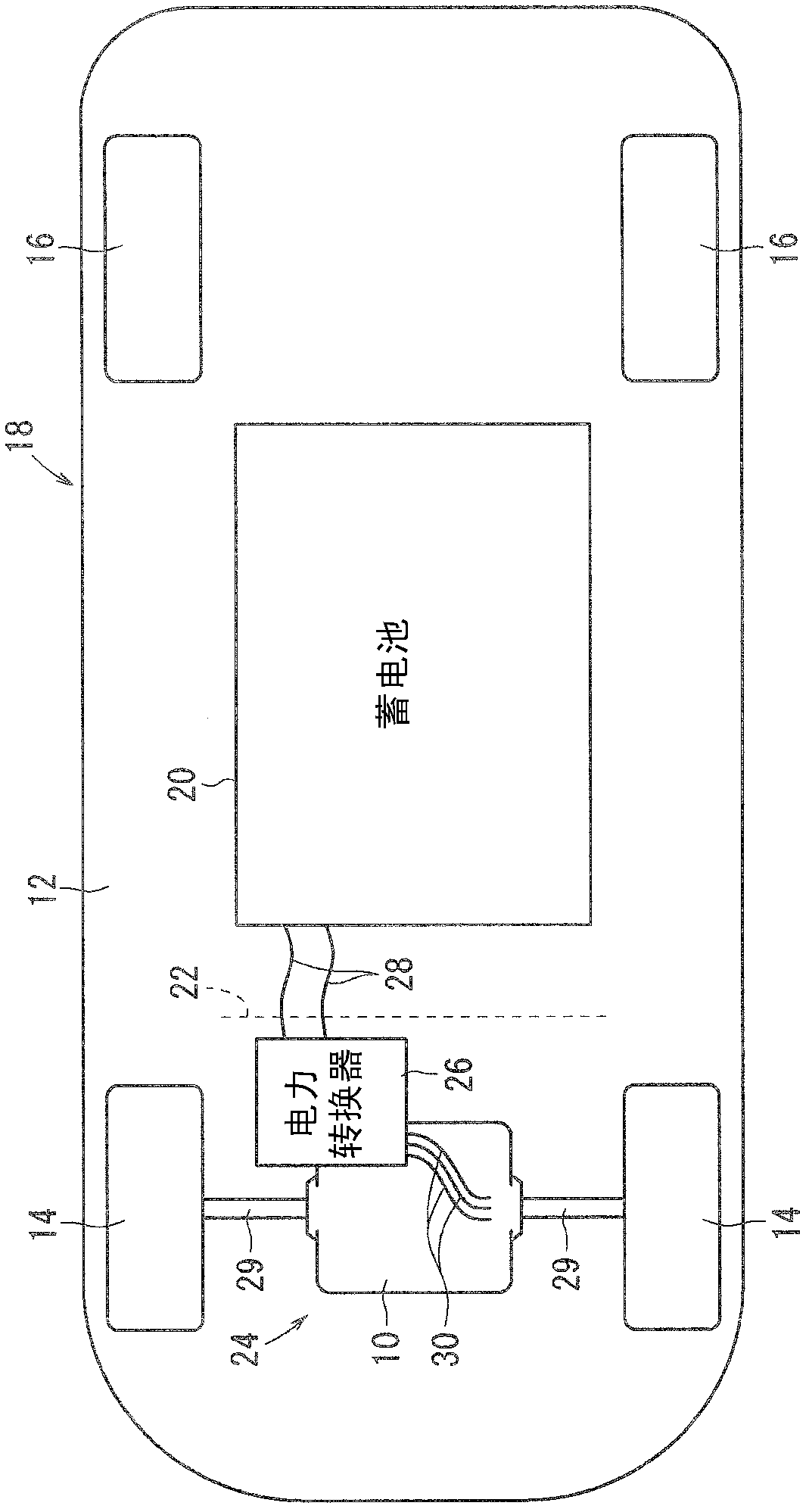
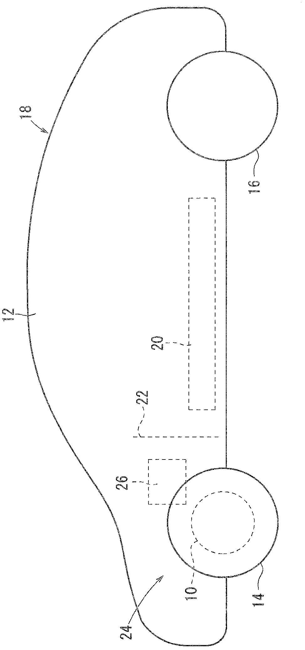
[0055] figure 1 Indicates that the rotating electric machine 10{of this embodiment functions as a motor or a generator. Hereinafter, it is called a motor for easy understanding. } A schematic plan view of a four-wheeled vehicle 18 (electric vehicle) including front wheels 14 and rear wheels 16 mounted on the vehicle body 12 . figure 2 A schematic side view of vehicle 18 is shown.

[0056] A battery 20 is disposed under a floor under unillustrated seats of the vehicle 18 . Motor 10 and power converter 26 are mounted in motor room 24 of vehicle 18 forward of dashboard lower panel 22 , and the rotation of the rotation shaft of motor 10 is transmitted to axle 29 that rotates left and right front wheels 14 .

[0057] Two DC power lines 28 are connected between a power converter 26 mounted vertically above the motor 10 and the battery 20 , and three AC three-phase power l...


PUM


Abstract

The invention provides a rotary motor, which has a structure that a conductive member is fixedly disposed in a housing. A power converter disposed on an outer side of the housing of the rotary motor and a rotary motor body accommodated in the inside part of the housing. The conductive member can serve as a relay between the above mentioned two parts. A bolt inserted into an opening part of the housing can be used to fix a power terminal onto the conductive member, and the bolt can not fall towards the inside of the housing, namely towards the rotary motor body. A barrier member (130) is disposed in the opening part (78) of the housing (46) of the rotary motor body (40) in an inwardly protruding manner. The conductive member (45) provided with the power terminal (92) and the barrier member (130) can be used to maintain the gap C between insulation members (56) to form a distance that the bolt (82) can not pass through.

Description

technical field [0001] The present invention relates to a rotating electrical machine (motor generator) that operates as a motor or a generator, and more particularly to a rotating electrical machine having a structure in which a power line from a power converter and a rotating electrical machine main body accommodated in a housing are connected. A conductive member for electrical connection between the power terminals is secured inside the housing. Background technique [0002] For a long time, as in Patent Document 1 figure 2 As shown, there is proposed a rotating electric machine (2) having a conductive part structure, and the conductive part structure is fastened to a power supply terminal connected to a stator coil (10) and one end thereof by a bolt (11a) to a power supply terminal supplied with power from a power converter. The other ends of the bus-bar-shaped terminals (9) on the wire harness (terminal) (6) are tightened to conduct conduction. [0003] [Patent Docum...

Claims


Application Information

Patent Timeline
IPC IPC(8): H02K5/22
CPCY02T10/641Y02T10/64
Inventor 樱田学
Owner HONDA MOTOR CO LTD
Learn More