
Display case for vibration powered device

A vibration-driven, motion-based technology that is applied to tracks for toys, automatic toys, toys, etc., and can solve problems such as low fidelity

Inactive Publication Date: 2012-07-11
INNOVATION FIRST INC
View PDF5 Cites 1 Cited by
  • Summary
  • Abstract
  • Description
  • Claims
  • Application Information

AI Technical Summary

Problems solved by technology

Extremely low-fidelity movement due to sliding and stiff reactions when hitting walls

Method used


Image

  • Display case for vibration powered device
  • Display case for vibration powered device
  • Display case for vibration powered device

Examples


Embodiment Construction

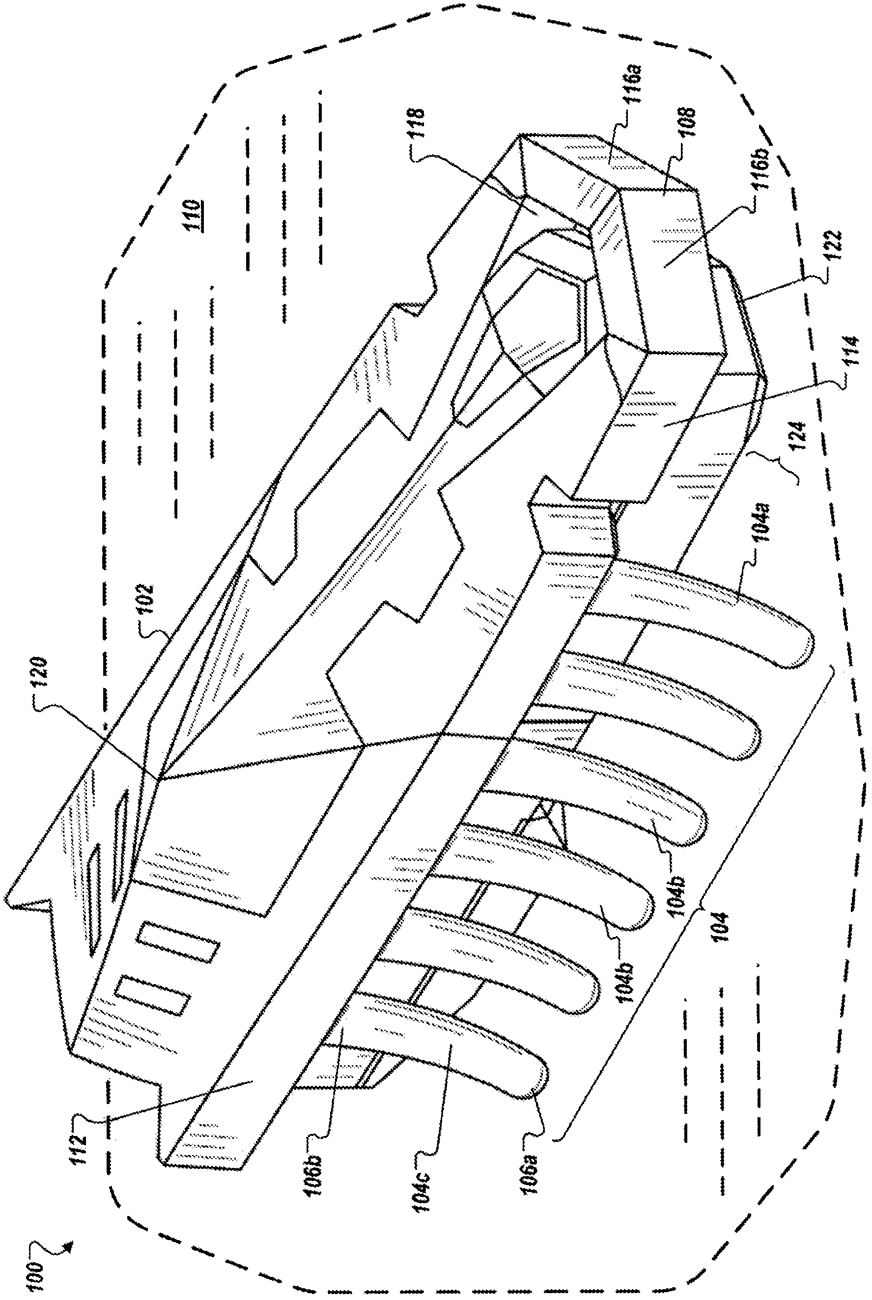
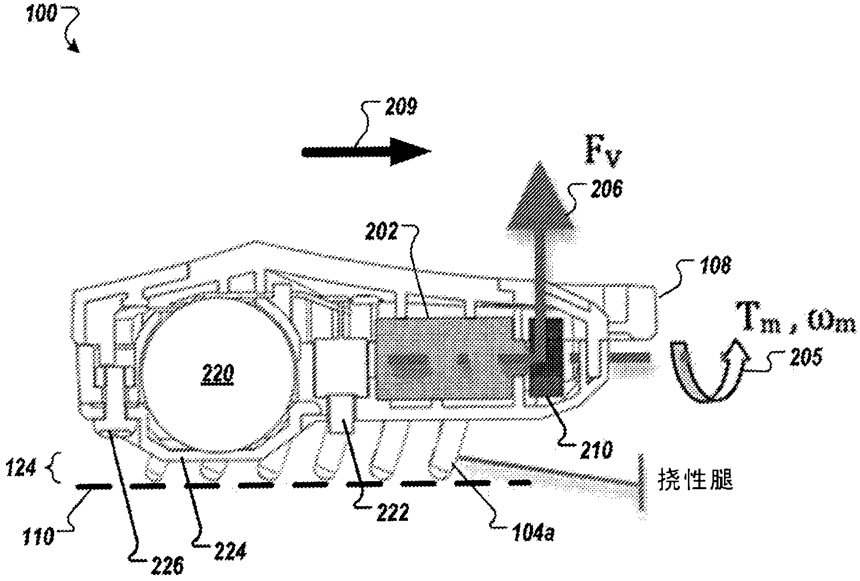
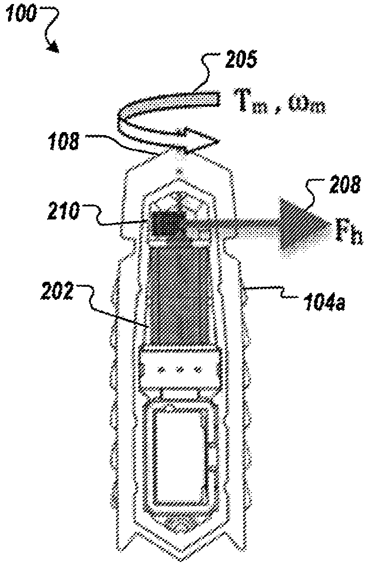
[0052] Small robotic devices or vibration-driven vehicles can be designed to move over surfaces such as floors, tabletops, or other relatively flat surfaces. Robotic devices are adapted to move autonomously and, in some applications, appear to turn in random directions. Typically, a robotic device includes a housing, a plurality of legs, and a vibration mechanism (e.g., a motor or spring-loaded mechanism to rotate an eccentric load, a motor or other mechanism adapted to induce oscillations of a counterweight, or other component settings where the centroid changes rapidly). Thus, small robotic devices can mimic organic life, such as beetles or insects, when they move.

[0053] The motion of the robotic device may be induced by the motion of a rotating electric motor within or mounted to the device in combination with a rotating counterweight arranged with a center of mass offset relative to the rotational axis of the motor. The rotational movement of the counterweight vibrate...


PUM


Abstract

An apparatus includes a fixed base, a platform supported by the fixed base, and a mechanism for causing vibration coupled to the platform and adapted to induce vibration of the platform sufficient to cause a vibration-powered vehicle to move across the platform without relying on an internal power supply of the vehicle. In some cases, a substantially planar cover is situated approximately parallel to the platform and spaced apart from the platform at a great enough distance to allow the vibration-powered vehicle to move across the platform and at a low enough distance to deter the vibration-powered vehicle from turning over.

Description

[0001] Citations for Associated Applications [0002] This application claims priority to U.S. Patent Application No. 61 / 246,023, filed September 25, 2009, entitled "Vibration Powered Vehicle," and filed August 20, 2010, entitled "Vibration Powered Vehicle." Priority to US Patent Application No. 12 / 860,696, and priority to US Patent Application No. 12 / 872,209, filed August 31, 2010, entitled "Vibration Powered Toy." The entire contents thereof are incorporated in this specification by reference. Background technique [0003] The present invention relates to display cases for devices that move based on oscillatory motion and / or vibration. [0004] An example of vibration-driven motion is a vibrating electronic soccer game. Bioplastic-free setups induced by vibrating horizontal metal surfaces are used for random or slightly directional movements. A recent example of vibration-driven motion uses an internal power source on a carrier along with a vibration mechanism. [0005]...

Claims


Application Information

Patent Timeline
Patent Type & Authority Applications(China)
IPC IPC(8): A63H18/00A63H11/02A63H17/26A63H29/22
CPCA63H18/08
Inventor 大卫·安东尼·诺曼罗伯特·H·米姆利特施三世约尔·瑞甘·卡特道格拉斯·迈克尔·加勒蒂保罗·大卫·科匹奥立
Owner INNOVATION FIRST INC
Learn More