
Testing drive for a stepping switch

A driving device and stepping switch technology, applied in electric switches, measuring devices, instruments, etc., can solve problems such as inspection and measurement cumbersome

Inactive Publication Date: 2012-07-11
MASCHFAB REINHAUSEN GEBR SCHEUBECK GMBH & CO KG
View PDF5 Cites 0 Cited by
  • Summary
  • Abstract
  • Description
  • Claims
  • Application Information

AI Technical Summary

Problems solved by technology

[0010] Before the step switch or switcher is put into operation and the adjustable transformer is connected, many checks and measurements are required, such as resistance measurement and conversion ratio measurement, which are cumbersome, also because the step switch or switcher has not yet After operating its motor drive or manual drive connection

Method used


Image

  • Testing drive for a stepping switch
  • Testing drive for a stepping switch
  • Testing drive for a stepping switch

Examples


Embodiment Construction

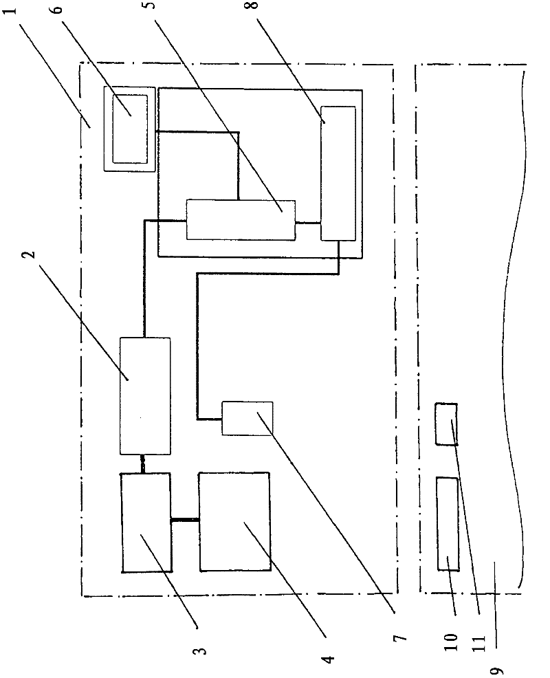
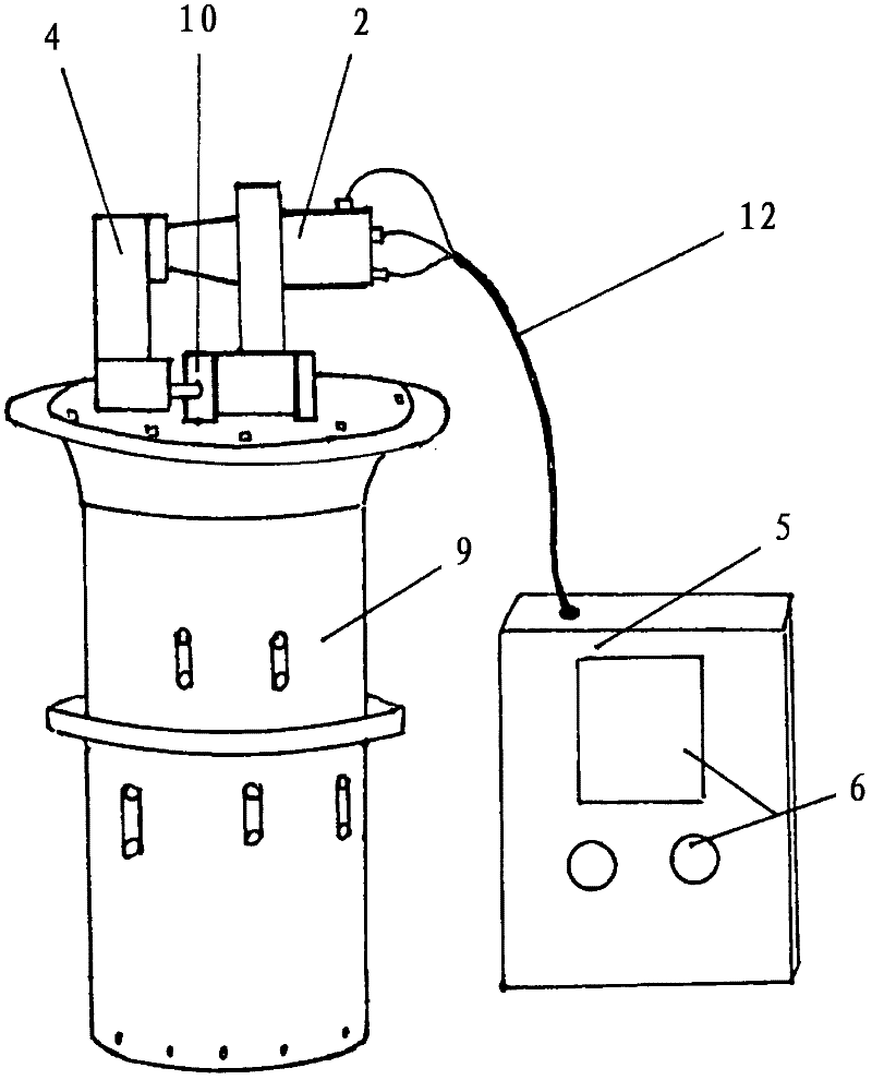
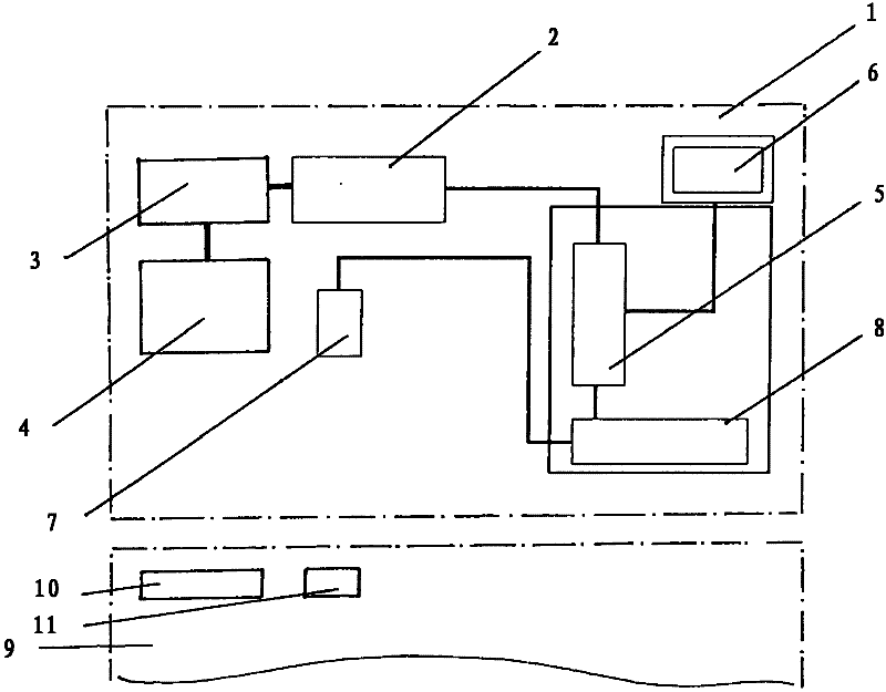
[0031] should first be based on figure 1 The illustration in illustrates the principle construction of the new test drive in more detail. The entire test drive 1 is surrounded here by a symbolic dashed line. The test drive has a servomotor 2 which acts on an adapter 4 via a transmission 3 . Furthermore, the test drive has a control unit 5 which cooperates with an operating unit 6 . Furthermore, a radio frequency identification (RFID) antenna 7 is provided, which is likewise connected to the control unit 5 via an RFID reader 8 . Below the test drive 1 , the upper part of the step switch 9 is likewise shown schematically here. There, an upper gear stage 10 is shown, to which the above-mentioned adapter 4 can be connected. Also shown is the likewise mentioned radio frequency identification tag 11 , which carries information about step switch-specific data and can be read by the radio frequency identification antenna 7 .

[0032] Thus, in the assembled state of the test drive...


PUM


Abstract

The invention relates to a testing drive for examining a stepping switch or a tap changer as part of transformer tests, wherein the testing drive has a servomotor that acts on an adapter by means of a gear train, wherein the adapter can be connected to the upper gear stage of the stepping switch or tap changer during the tests.

Description

technical field [0001] The invention relates to a test drive for testing step switches or switchers within the scope of testing transformers to be adjusted. Background technique [0002] Step switches are used to switch without interruption between winding taps of adjustable transformers. It has been known for many years in many embodiments, for example by the applicant's company in the printed document " VR-Laststufenschalter für Regeltransformatoren (for regulating transformers VR-on-load stepping switch)", print publisher IN206 / 09de-0708 / 1000. [0003] The step switch described there consists of an on-load switch housed in a separate oil container and a selector arranged below it. [0004] The selector is used to preselect the new winding tap that should be switched to of the adjustable transformer without power; the on-load switcher is used to follow the ground, quickly, without interruption, and truly switch from the previous winding tap to the new winding tap . ...

Claims


Application Information

Patent Timeline
IPC IPC(8): G01R31/327
CPCG01R31/3274H01H9/0005G01R31/3272H02P13/06G01R31/327
Inventor A·比林格尔
Owner MASCHFAB REINHAUSEN GEBR SCHEUBECK GMBH & CO KG
Learn More