Curved compensating transformer and its phase-shift voltage regulating method

A transformer and zigzag technology, applied in the field of motor and transformer disciplines, can solve problems such as inconvenient structure and complexity, and achieve the effect of easy on-load voltage regulation and energy-saving transformation

Inactive Publication Date: 2002-10-23
刘建平
View PDF1 Cites 18 Cited by
  • Summary
  • Abstract
  • Description
  • Claims
  • Application Information

AI Technical Summary

Problems solved by technology

However, when this six-phase voltage regulator is used as a compensating voltage regulating device for a power transformer, the

Method used


Image

  • Curved compensating transformer and its phase-shift voltage regulating method
  • Curved compensating transformer and its phase-shift voltage regulating method
  • Curved compensating transformer and its phase-shift voltage regulating method

Examples


Embodiment 1

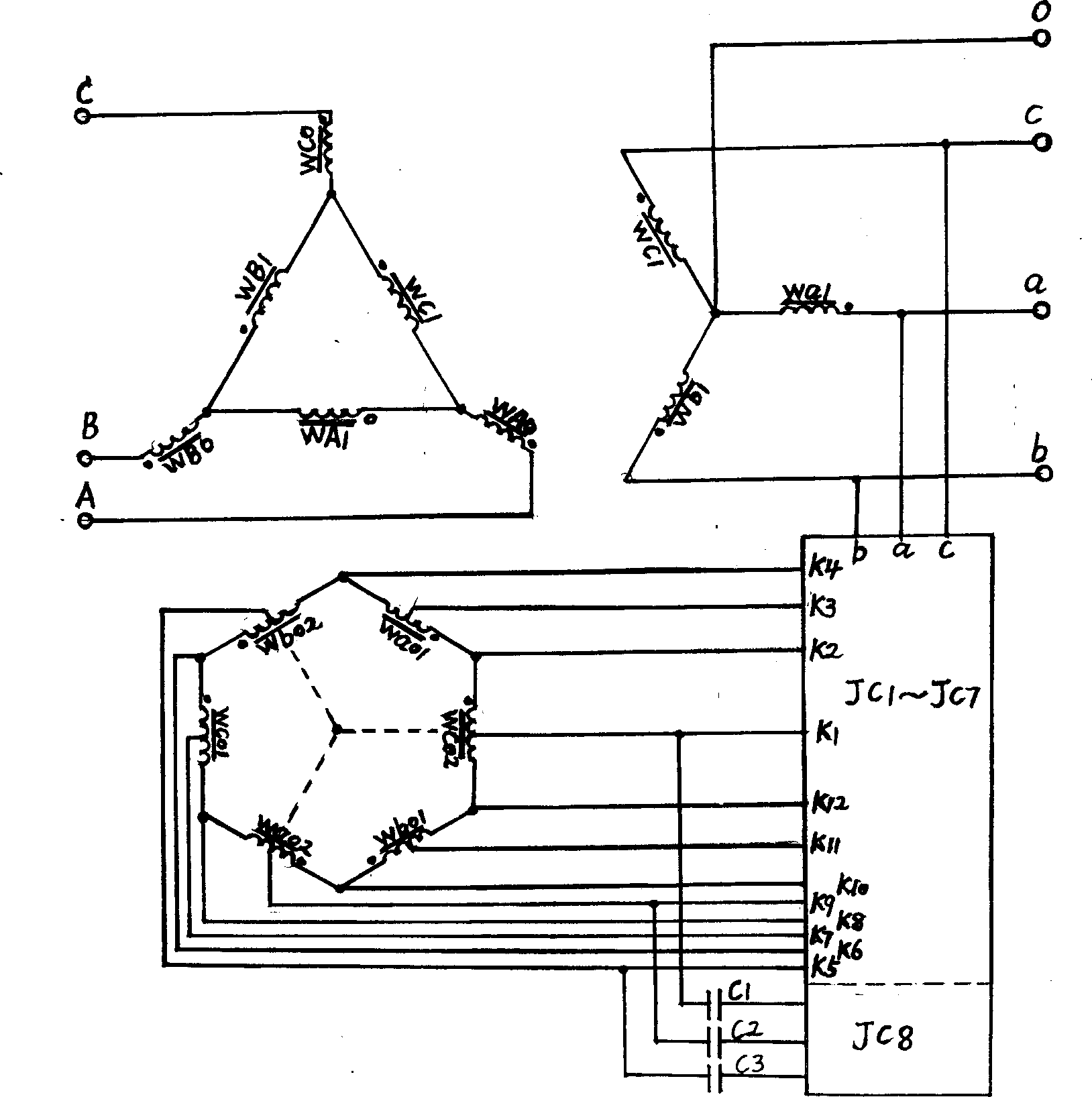
[0012] In this example, the design voltage ratio of the distribution transformer is 10 / 0.4KV, and the voltage is adjusted to ±6×2.5%UH. The iron core is arranged on the upper part, and the cross-sectional ratio of the two iron cores can be taken as 2:1. WAo, WBo, and WCo high-voltage windings are respectively installed in the three core columns of the adjusting core, and correspondingly installed with Wao1 and Wao2, Wbo1 and Wbo2, Wco1 and Wco2 low-voltage windings, and K3 and K9, K11 and K5 are respectively drawn out in the middle of the low-voltage windings. , K7 and K1 regulation terminals. Three pairs of high and low voltage windings, WA1 and Wa1, WB1 and Wb1, WC1 and Wc1, are respectively installed on the three cores of the main body. The wiring method of the high-voltage combined winding is: the first end (end of the same name) of the winding of WA1, WB1 and WC1 is connected to the end of the previous winding (the end of the same name) to form a delta connection, and it...

Embodiment 2

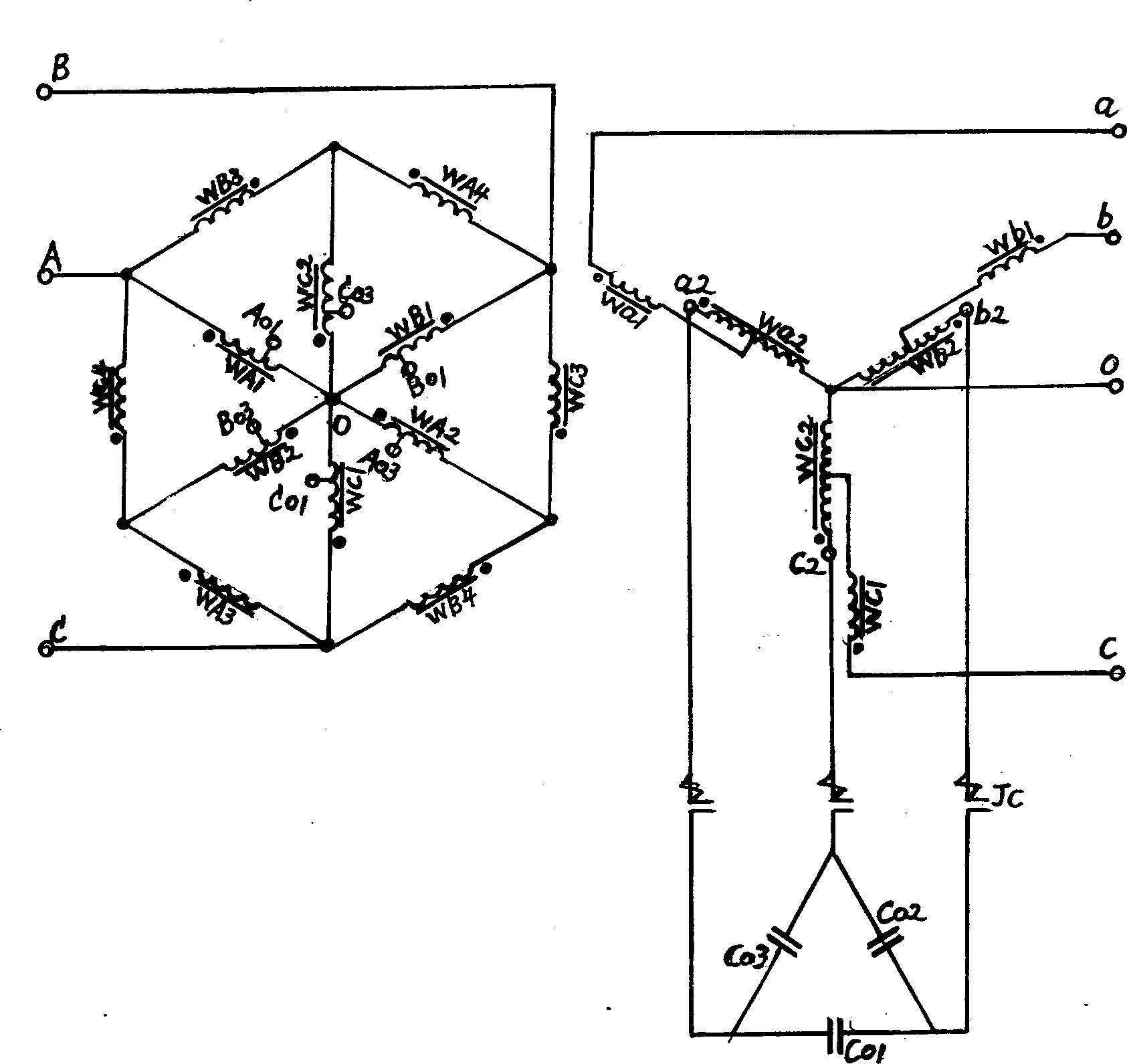
[0014] Embodiment 2 In this example, the transformer voltage ratio is designed to be 10 / 0.4KV, and the voltage adjustment range is +7×2.5% to -4×2.5% UH. The iron core and winding are designed as follows: the main iron core and the adjustment iron core placed on the upper part adopt a conjugate "Tian"-shaped combined structure, the upper and lower core columns are equal to the core cross-sections of the upper and lower cross yokes, and the middle cross yoke is larger than the iron core of the core column. The ratio of the cross-sectional area is 1:3, and the window height of the upper and lower iron cores is 1:1.5; the cross-sectional ratio of the high-voltage winding of the main core and the high-voltage winding of the regulating core is √3:1, and the ratio of turns of the corresponding low-voltage winding is also √3∶1; the low-voltage winding of the adjusting iron core increases the number of turns by √3 times in the form of self-coupling; WA2 and WA4, WB2 and WB4, WC2 and WC...


PUM


Abstract

This invention applies a combination structure of two three-phase iron core and double winding by switching low voltage side hexagon to regulate the winding or high voltage side six starlike ones regulate the level, so makes the voltage phasor relatively zigzag shift between the winding of the regulated sore and the host core and realizes on-load voltage regulation and the auxiliary voltage regulation by way of compensation within capacitors. It has the advantages of low cost of regulation devices, small volume of tap switching and high power factor, which is suitable for producing new type of on-load regulation voltage transformer and the reform.

Description

1. Technical field [0001] The invention belongs to the subject field of motor transformers, in particular to a meander compensation transformer and a phase-shifting voltage regulation method. 2. Background technology [0002] The current voltage regulation principle of the transformer is mainly to use a method of changing the turns ratio of the winding to make the magnetic flux in the iron core change numerically, so as to achieve the purpose of voltage regulation. This straight-line voltage regulation method inevitably bears the problem of high voltage and large breaking capacity during the switching process of the tap changer. A conventional on-load tap changer must use an on-load tap-changer consisting of an operating mechanism, a fast mechanism, a diverter switch and a selector switch. The complexity and high cost of the device limit its use in small and medium-sized power distribution. Widely used in the field of transformers. With the improvement of power supply qual...

Claims


Application Information

Patent Timeline
IPC IPC(8): H01F29/04
Inventor 刘涛刘建平杨健刘三平张秀康
Owner 刘建平
Why Eureka
Try Eureka