Vehicle exhaust waste heat thermoelectric conversion vehicle power supply system and control method

A technology for thermoelectric conversion and automobile exhaust, which is applied in electric vehicles, battery circuit devices, generators/motors, etc., and can solve the problems of difficult optimal working state of thermoelectric conversion modules, cost-effective device discount, and long additional cost recovery period.

Inactive Publication Date: 2011-12-14
WUHAN UNIV OF TECH
View PDF6 Cites 30 Cited by
  • Summary
  • Abstract
  • Description
  • Claims
  • Application Information

AI Technical Summary

Problems solved by technology

Most of the current automobile exhaust waste heat thermoelectric power generation devices have the problem of low conversion efficiency and conversion power. Although part of the waste heat in the exhaust gas can be recovered, the converted power is only tens to hundreds of watts, and the generated electricity is only enough. Some on-board electrical appliances are used, so the recovery period of the additional cost invested in the car is longer
In addition, in many thermoelectric conversion devices developed, the waste heat in the exhaust gas of automobile engines has not been effectively absorbed, and some thermoelectric conversion modules are difficult to be in the optimal working state due to the temperature difference between the cold and hot ends, which greatly reduces the cost performance of the devices

Method used


Image

  • Vehicle exhaust waste heat thermoelectric conversion vehicle power supply system and control method
  • Vehicle exhaust waste heat thermoelectric conversion vehicle power supply system and control method
  • Vehicle exhaust waste heat thermoelectric conversion vehicle power supply system and control method

Examples


Embodiment Construction

[0030] The present invention will be further described below in conjunction with the accompanying drawings and embodiments, but these embodiments should not be construed as limiting the present invention.

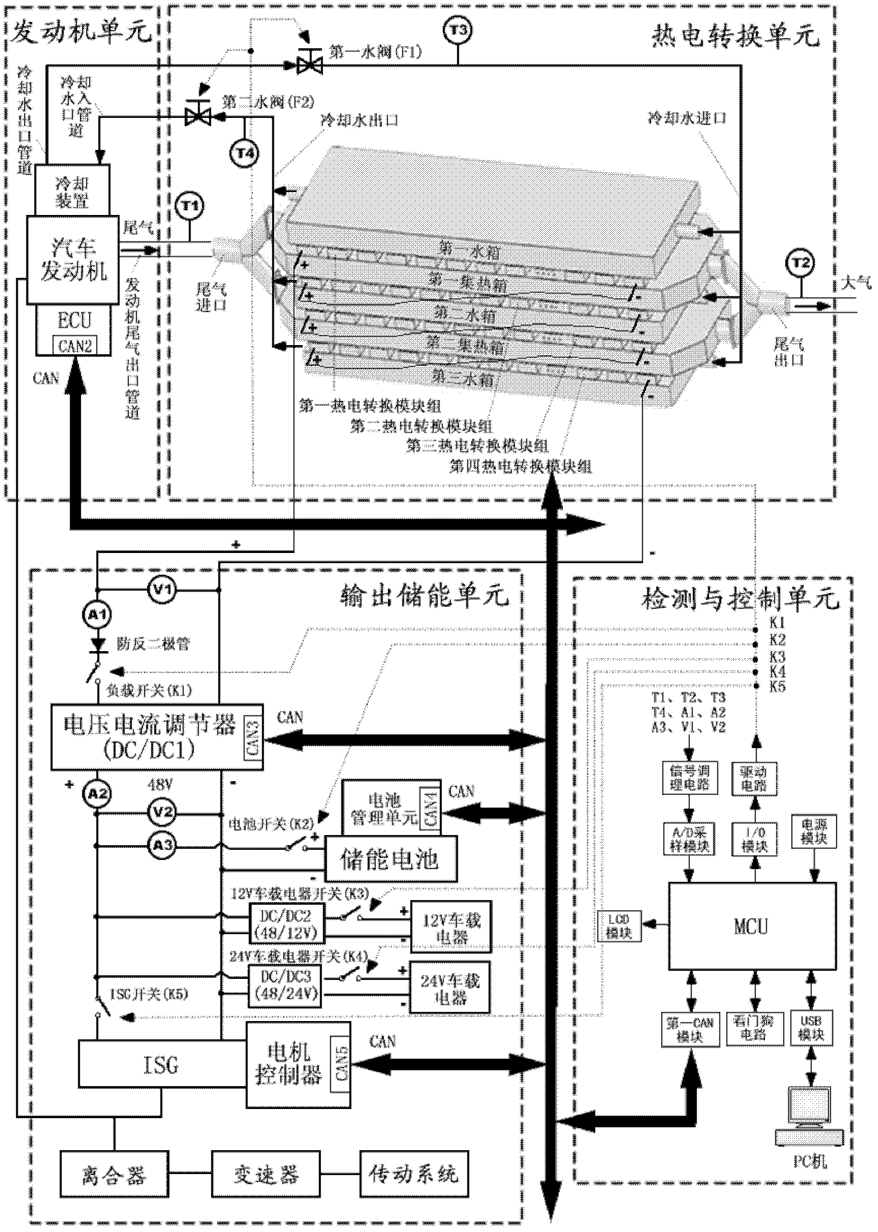
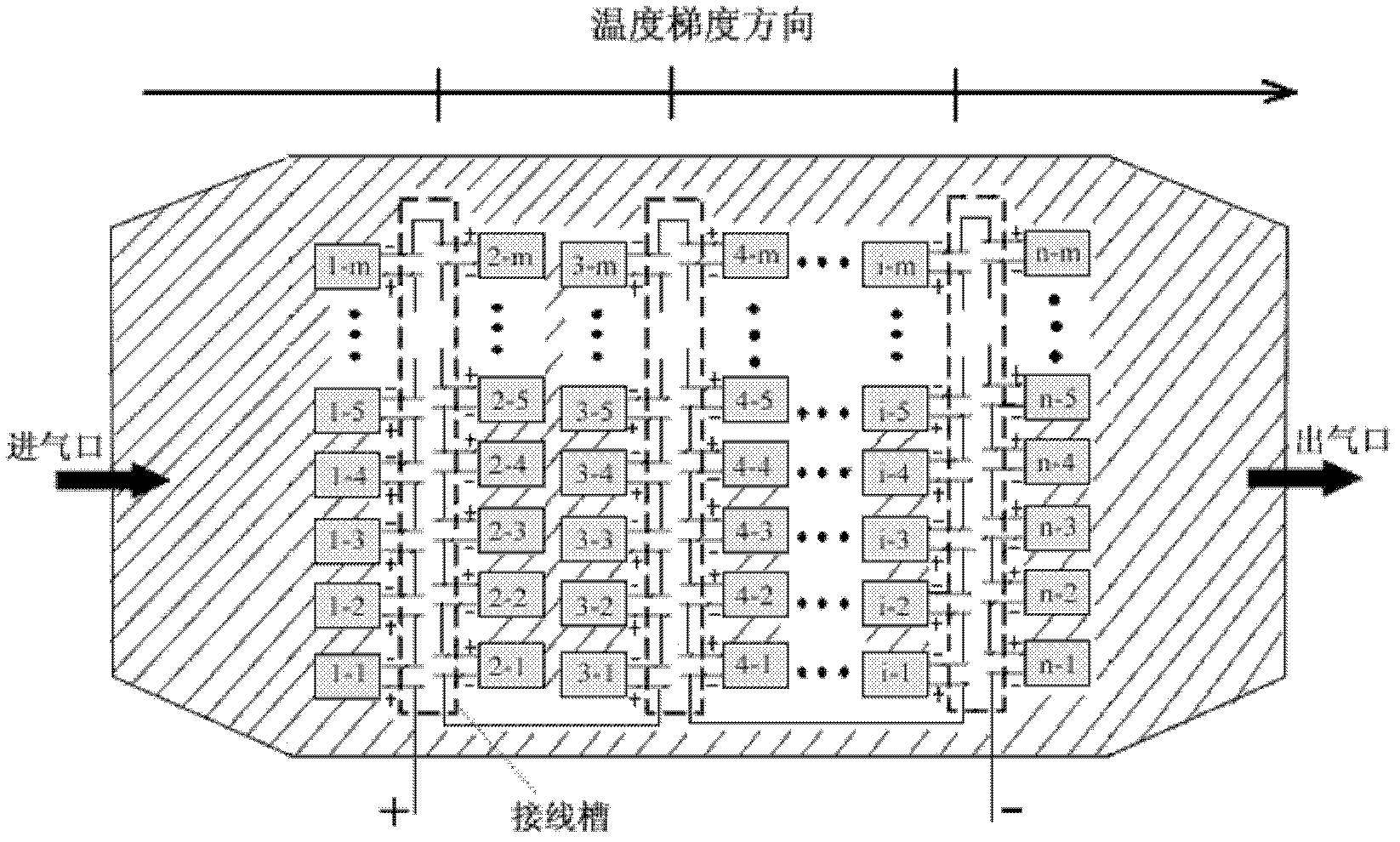
[0031] The main part of the present invention is made up of engine unit, thermoelectric conversion unit, output energy storage unit detection and control unit (as figure 1 shown), wherein: the engine unit sends the high-temperature exhaust gas discharged from the automobile engine and the cooling water in the cooling device into the thermoelectric conversion unit for heat transfer; the hot end of the thermoelectric conversion module in the thermoelectric conversion unit is in contact with the heat collector to absorb The heat, the cold end of which is in contact with the water tank is cooled by the cooling water flowing inside, so that the temperature difference between the hot and cold ends of the thermoelectric conversion module is constructed to generate DC power for outp...


PUM


Abstract

The invention relates to a thermoelectric conversion automotive power supply system using waste heat from automobile exhaust and a control method thereof, wherein the system is composed of an engine unit, a thermoelectric conversion unit, an output and electric energy storage unit and a detection and control unit. The system is characterized in that high temperature exhaust is discharged during the running of the engine and cooling water in a certain temperature range is provided; the heat brought by the high temperature exhaust is absorbed by hot terminals of a plurality of thermoelectric modules connected in series in the thermoelectric conversion unit, and cold terminals of the thermoelectric modules form temperature difference between the hot terminals and the cold terminals under thecooling effect of the cooling water of the automotive engine, so as to generate direct-current electric energy; the voltage and the current of the electric energy generated from the thermoelectric conversion unit are regulated by the output and electric energy storage unit, and the electric energy is used to supply on-vehicle appliances and ISG or charge the energy storage battery; the detection and control unit is used for detecting parameters, sending a control command and performing comprehensive energy management on the system. The system effectively recycles and utilizes the waste heat from the automobile exhaust, improves the economical efficiency of the fuel of the automotive engine, and is contributed to reducing the automobile exhaust emission.

Description

technical field [0001] The invention belongs to a vehicle-mounted power supply system and a control method, in particular to a vehicle-mounted power supply system and a control method for thermoelectric conversion of waste heat from automobile exhaust. Background technique [0002] The rapid development of society has greatly increased the demand for energy, and traditional energy is increasingly scarce. Seeking efficient and pollution-free clean energy or secondary recovery and utilization of traditional energy has become an effective way to solve today's energy and environmental problems. [0003] At present, the power conversion efficiency of automobiles is only about 40%, and as many as 60% of the energy in the fuel is not effectively utilized, and the heat taken away by the engine exhaust accounts for about 30% to 45% of the fuel combustion heat. The cooling heat accounts for about 30%, and most of these energy are lost to the air in the form of waste heat, resulting in...

Claims


Application Information

Patent Timeline
Patent Type & Authority Applications(China)
IPC IPC(8): H02N11/00H02J7/00B60L11/00
Inventor 全睿唐新峰全书海黄亮张清杰邓亚东苏楚奇翟鹏程王月
Owner WUHAN UNIV OF TECH
Why Eureka
Try Eureka