Heat-pump-driven solution dehumidifying air-conditioning device

A solution dehumidification air conditioner and solution dehumidification technology, applied in the field of air conditioning, can solve the problems of low heat pump cycle efficiency and low heat absorption temperature, and achieve the effects of improving efficiency, increasing energy storage, and increasing the temperature of cold sources

Inactive Publication Date: 2010-05-05
SOUTHEAST UNIV
View PDF0 Cites 26 Cited by
  • Summary
  • Abstract
  • Description
  • Claims
  • Application Information

AI Technical Summary

Problems solved by technology

The biggest defect of this device is: due to the limitation of ambient temperature, the heat pump evaporator in the

Method used


Image

  • Heat-pump-driven solution dehumidifying air-conditioning device
  • Heat-pump-driven solution dehumidifying air-conditioning device
  • Heat-pump-driven solution dehumidifying air-conditioning device

Examples


Example Embodiment

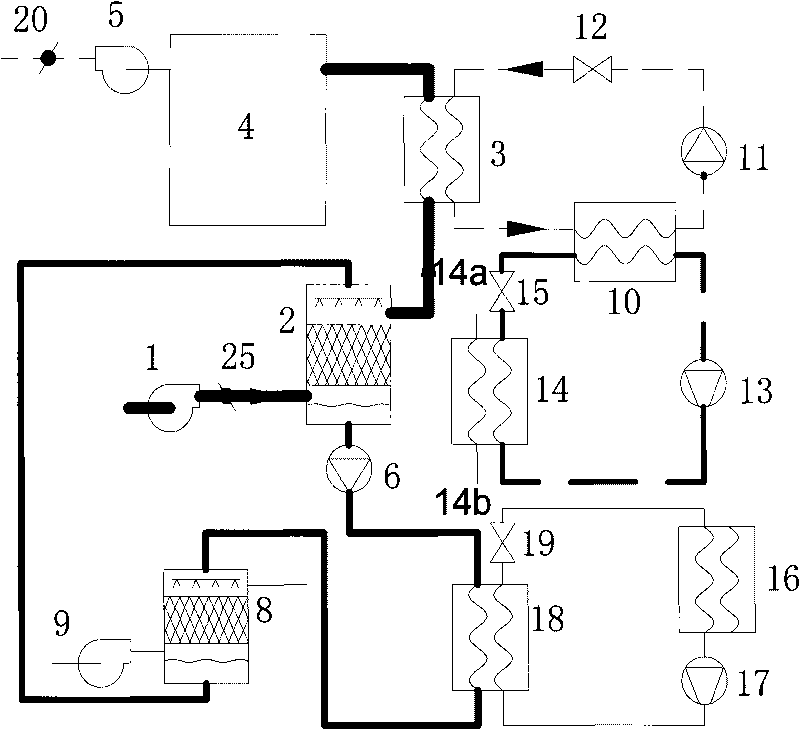
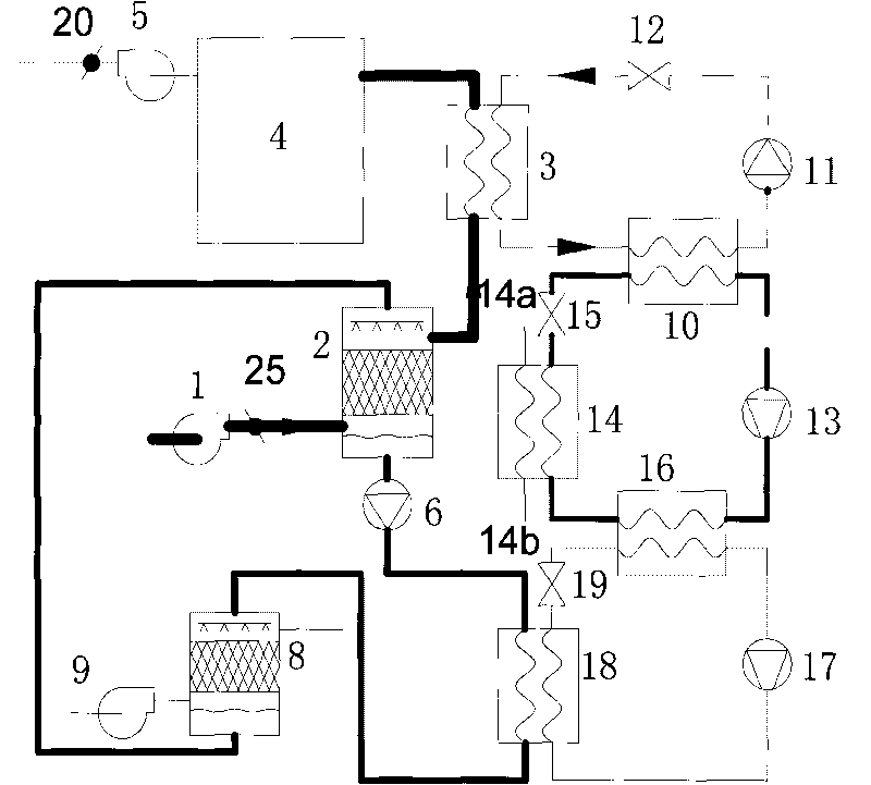
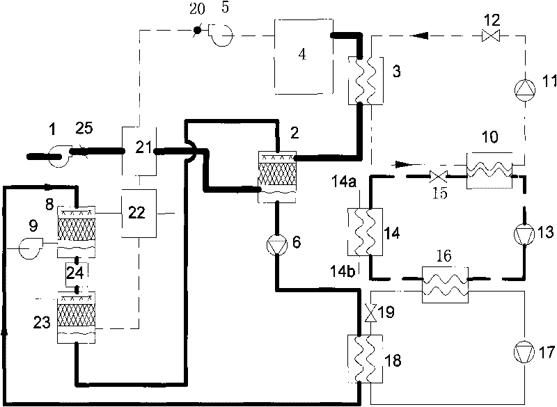
[0033] Such as figure 2 As shown, the solution dehumidification air conditioning device of the present invention includes a solution dehumidification component, an air treatment system component, a refrigeration component, and a heat pump component.

[0034] Air handling system components, including outdoor air system components, exhaust system components and fresh air system components. Among them, outdoor air system components include outdoor fan 9; exhaust system components include exhaust fan 5 and exhaust valve 20; fresh air system components include fresh fan 1, fresh air valve 25, water-air heat exchanger 3 and air-conditioned room 4. The output end of the fresh air blower 1 is connected to the input end of the fresh air valve 25, the output end of the fresh air valve 25 is connected to the first input end of the solution dehumidifier 2 in the solution dehumidification assembly, and the first output end of the solution dehumidifier 2 is connected to the water- The first i...


PUM


Abstract

The invention provides a heat-pump-driven solution dehumidifying air-conditioning device, comprising a solution dehumidifying component, an air processing system component, a refrigerating component and a heat pump component; the solution dehumidifying component is formed by a solution pump, a heat pump condensing pipe, a one-level solution regenerator and a solution dehumidifying device which are connected; the air processing system component comprises an outdoor blower, an exhaust blower, an exhaust valve, a new blower, a new air valve, a water-air heat exchanger and an air conditioning room; in the refrigerating component, a refrigeration evaporator, a freezing water circulating pump and a freezing water adjusting valve are connected with the water-air heat exchanger to form freezing water circulation; a refrigerating compressor, a refrigerating condenser and a refrigerating throttling valve are connected with the refrigeration evaporator to form refrigerating circulation of a cold water unit. The heat pump component is formed by a heat pump compressor, a heat pump condenser, a heat pump throttling valve and a heat pump evaporator which are connected, wherein the heat pump evaporator is connected between the refrigerating compressor and the refrigerating condenser. The air-conditioning device improves the heat adsorption temperature of the heat pump evaporator and improves the heating efficiency.

Description

technical field [0001] The invention belongs to the field of air conditioning, and in particular relates to a solution dehumidification air conditioning device driven by a heat pump. Background technique [0002] With the development of society, the energy consumption of HVAC continues to increase. This depletes fossil energy sources and causes an environmental crisis on a global scale. The development of new high-efficiency refrigeration equipment and system optimization design has become an important direction to solve this problem. At present, air-conditioning devices with independent control of temperature and humidity based on solution dehumidification have been applied in practice. [0003] Such as figure 1 As shown, such an apparatus includes a solution dehumidification assembly, an air handling system assembly, a refrigeration assembly, and a heat pump assembly. [0004] Solution dehumidification components include solution pump, heat pump condenser, primary solu...

Claims


Application Information

Patent Timeline
IPC IPC(8): F24F3/00F24F3/14F24F12/00F24J2/00
CPCY02E10/40
Inventor 陈九法乔卫来薛琴郑红旗安二铭
Owner SOUTHEAST UNIV
Why Eureka
Try Eureka