Method for controlling voltage reactive variables of high-voltage power grid transformer substation

A technology of voltage and reactive power and control methods, which is applied in the directions of reactive power compensation, reactive power adjustment/elimination/compensation, etc., can solve the mismatch of reactive power and voltage control conditions, and does not consider the influence of active power on the voltage and reactive power control range , did not consider the relationship between reactive power and voltage, etc.

Active Publication Date: 2012-07-18
STATE GRID CORP OF CHINA +2
View PDF2 Cites 10 Cited by
  • Summary
  • Abstract
  • Description
  • Claims
  • Application Information

AI Technical Summary

Problems solved by technology

[0003] The nine-zone diagram is based on the most basic relationship algorithm between the voltage and reactive power on both sides of the transformer. It has the advantages of simple relationship and clear purpose. The power grid operation control conditions are determined, so the reactive power control range of the substation should be determined according to the voltage control range. (2) The nine-area diagram does not consider the mutual influence of the relationship between voltage and reactive power changes, and the area division and control method are too simple, which may easily cause reciprocating action
Due to the increase or decrease of the voltage after switching the capacitor / reactor, the operating point moves to another unsatisfied area, which is a prominent problem in the current nine-zone diagram algorithm; (3) The control of active power on voltage and reactive power is not considered range of impact

Method used


Image

  • Method for controlling voltage reactive variables of high-voltage power grid transformer substation
  • Method for controlling voltage reactive variables of high-voltage power grid transformer substation
  • Method for controlling voltage reactive variables of high-voltage power grid transformer substation

Examples


Embodiment 1

[0159] Example of the relationship between the voltage and reactive power variables of the substation in step D:

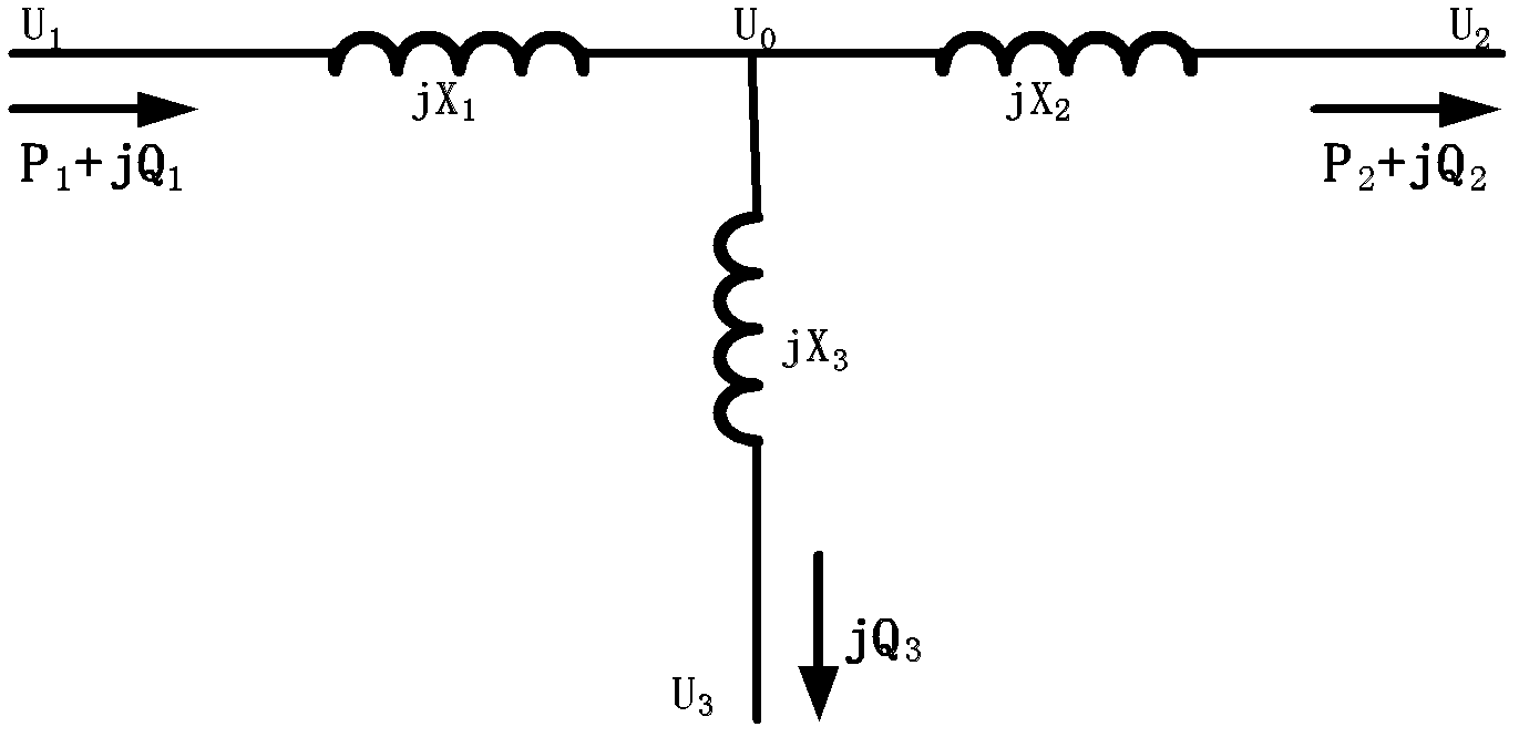
[0160] Table 1 shows the grid simulation calculation results of transformer voltage and reactive power under the condition of transmitting different active power in UHV substations and the calculation results of applying expression (9), in which, in expression (9), U 2 and Q 1 Using the simulation results, U 1 The calculated value of Expression (9) is compared with the simulation calculation result. It can be seen from the table that when the transformer load is large, ignoring the influence of active power will cause a certain deviation in the calculation result of expression (9).

[0161] Table 1 Comparison of the calculation results of the substation voltage and reactive power formula with the simulation calculation results

[0162]

[0163] In the embodiment, according to the above calculation results, under different load rates of the transformer, the c...

Embodiment 2

[0168] In step E, the substation voltage and reactive power control strategy judgment value range embodiment:

[0169] In the embodiment, the voltage control range of the high-voltage side and the medium-voltage side of the substation is specified as follows during the operation of the power grid:

[0170] High pressure side U 1 : 0.952p.u.~1.029p.u.

[0171] Medium pressure side U 2 : 0.971p.u.~0.996p.u.

[0172] Reactive power Q is obtained from expressions (10) to (13) 1 The control range is shown in Table 3:

[0173] Table 3 Calculation results of reactive power control threshold in substations

[0174]

[0175] In the embodiment, the control requirement of reactive power hierarchical partition is not proposed, so it is not considered and control threshold.

[0176] From the simulation calculation results, it is determined that the transformer voltage and reactive power change range caused by switching one group of low-voltage reactive power compensation equip...

Embodiment 3

[0182] The embodiment of the substation voltage and reactive power control strategy in step F:

[0183] Table 4 shows the simulation calculation results of verifying the voltage and reactive power control strategy of the thirteen-area diagram in the present invention by performing the switching operation of the low-voltage reactive power compensation equipment in the UHV substation under different voltage and reactive power conditions. The simulation calculation results show that the voltage and reactive power control strategy of the thirteen-area diagram in the present invention can accurately adjust the voltage and reactive power of the substation within the control range, and avoid the phenomenon of repeated switching of reactive power compensation equipment.

[0184] Table 4 The simulation calculation results of the voltage and reactive power control strategy of the substation

[0185]

[0186] The method for controlling the voltage and reactive power variables of the h...


PUM


Abstract

The invention belongs to the technical field of voltage and reactive control for an electric system and particularly relates to a method for controlling voltage reactive variables of a high-voltage power grid transformer substation. The method comprises the following steps of: A, determining an application condition of a transformer element; B, establishing a mathematical model for the transformer element; C, taking a mathematical expression reduction result from the mathematical model; D, determining the voltage reactive variables of the transformer substation and calculating the relationship among the reactive variables; E, determining a control range of the voltage reactive variables of the transformer substation; and F, providing a control strategy for the voltage reactive variables of the transformer substation. The control method disclosed by the invention has the advantages of strong operability, complete consideration and rational scheme and has high practical value and good market prospect.

Description

technical field [0001] The invention belongs to the technical field of power system voltage and reactive power control, and in particular relates to a method for controlling voltage and reactive power variables of high-voltage grid substations. Background technique [0002] The traditional substation voltage and reactive power control strategy mainly divides the relationship between voltage and reactive power into 9 areas (that is, the nine-area diagram). Adjustment control of reactive equipment. [0003] The nine-area diagram is based on the most basic relationship algorithm between the voltage and reactive power on both sides of the transformer. The advantage is that the relationship is simple and the purpose is clear. However, in the actual operation process, there are the following shortcomings: (1) The voltage control range of the substation is mostly determined by The power grid operation control conditions are determined, so the reactive power control range of the su...

Claims


Application Information

Patent Timeline
Patent Type & Authority Applications(China)
IPC IPC(8): H02J3/18
CPCY02E40/30
Inventor 吴丽华王青李再华侯雪李晓珺陈得治
Owner STATE GRID CORP OF CHINA
Why Eureka
Try Eureka