
A steering system and a catcher system

A technology for manipulating systems and catheters, which is applied in the field of catheter systems and can solve problems such as the limitation of the number of rotations of catheters

Inactive Publication Date: 2012-07-18
KONINKLIJKE PHILIPS NV
View PDF5 Cites 18 Cited by
  • Summary
  • Abstract
  • Description
  • Claims
  • Application Information

AI Technical Summary

Problems solved by technology

The disadvantage of this is that the number of rotations of the conduit is limited by the axial size of the drum

Method used


Image

  • A steering system and a catcher system
  • A steering system and a catcher system
  • A steering system and a catcher system

Examples


Embodiment Construction

[0029] In the ensuing description of the preferred embodiments, reference is made to the accompanying drawings which form a part hereof. Specific examples in which the invention can be practiced are shown by way of illustration in the ensuing description. It is also to be understood that other embodiments may be utilized and structural changes may be made without departing from the scope of the present invention. It will be appreciated that the same reference numerals are used to refer to the same or similar parts in the various embodiments.

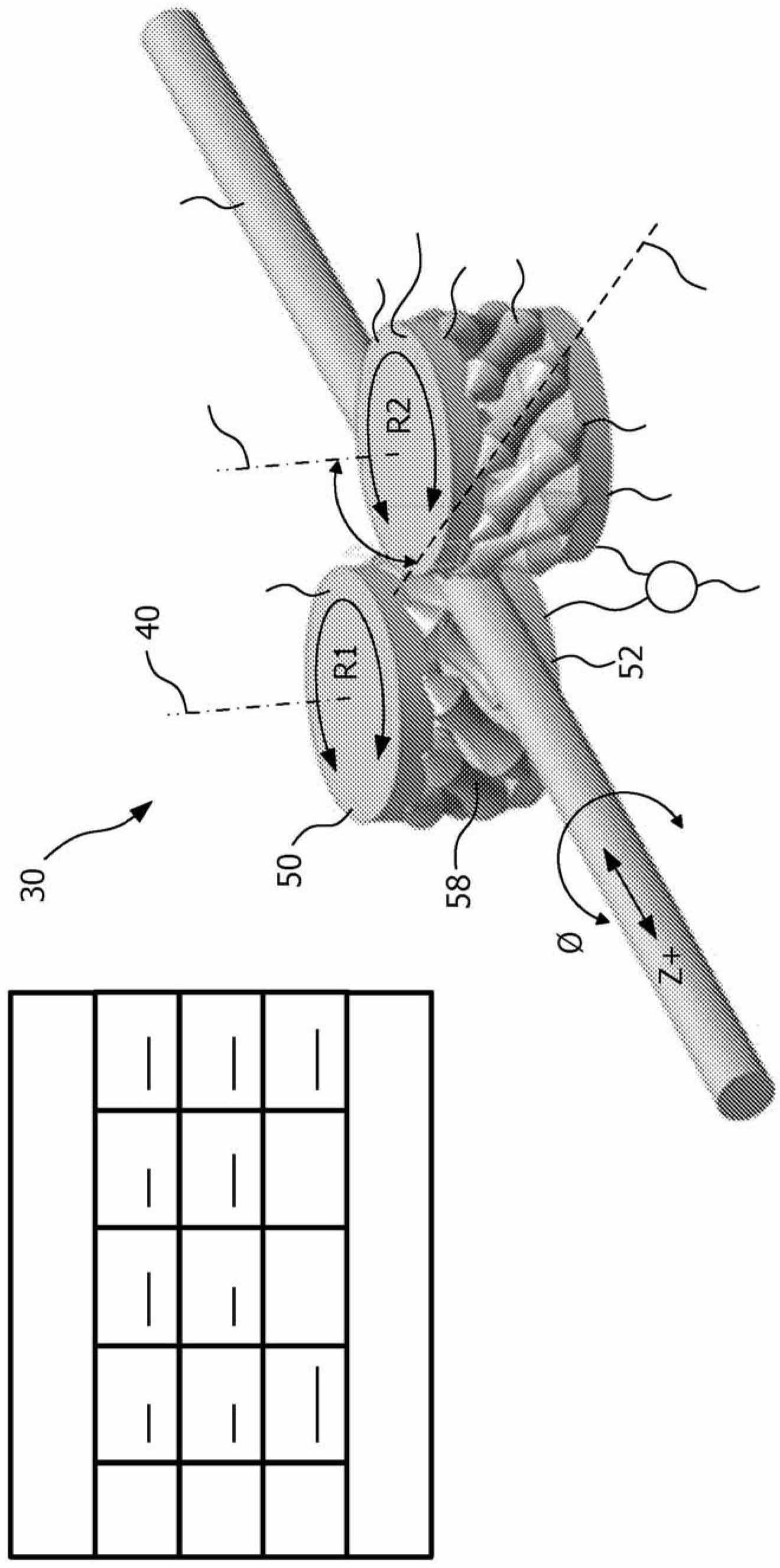
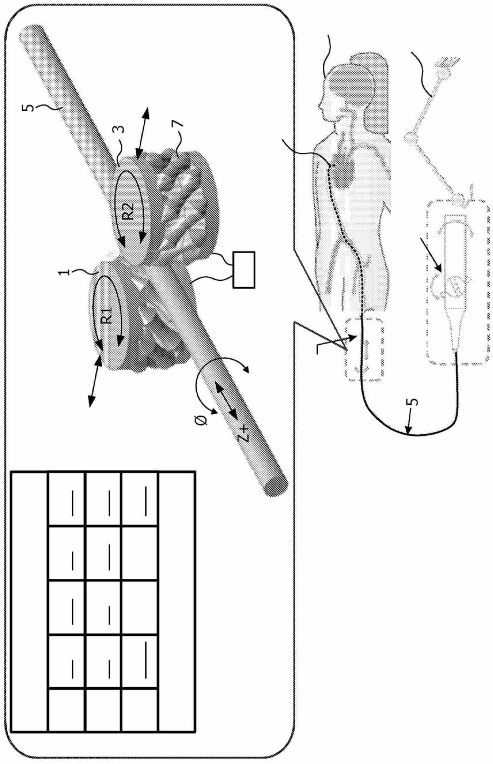
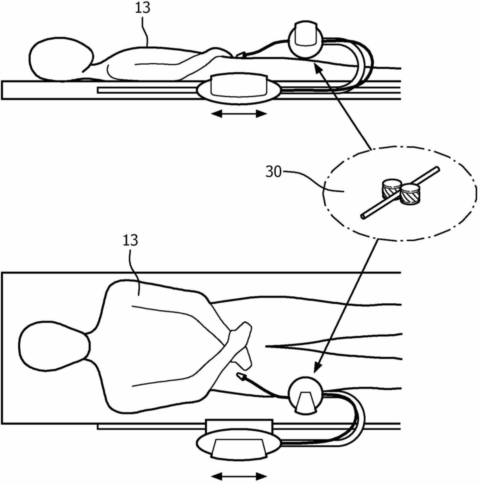
[0030] figure 1 The first embodiment of the invention shown in is shown in perspective view. The handling system 30 comprises two diametrically opposite drive wheels 1; 3 for handling the tubular object 5 located between the drive wheels 1; 3. The drive wheels 1 ; 3 respectively have a wheel axis of rotation 40 ; 42 and each drive wheel comprises a plurality of rollers 7 distributed around the wheel axis of rotation 40 ; 42 . In this...


PUM


Abstract

A steering system (30) comprises two radially oppositely arranged drive wheels (1; 3) for steering a tubular object (5) positioned between the drive wheels (1; 3). The drive wheels (1; 3) each have a wheel rotation axis (40; 42) and each include a plurality of rollers (7) distributed around the wheel rotation axis (40; 42). The rollers (7) are rotatably arranged, each roller having a roller rotation axis (44) and an outer drive face (58) concavely vaulted in a direction corresponding to its roller rotation axis (44). The roller rotation axis (44) is obliquely oriented in relation to the wheel rotation axis (40; 42) and the rollers (7) of each drive wheel (1; 3) form together a steering periphery for the tubular object (5). The steering system enables continues rotation of a tubular object without danger that the object will lose the contact with the rollers. The steering system (30) may be incorporated in a catheter system which comprises a catheter (5).

Description

technical field [0001] The invention relates to a handling system comprising two diametrically opposed drive wheels for handling a tubular object located between the drive wheels. [0002] The invention also relates to a catheter system comprising such a steering system. Background technique [0003] An example of such a steering system, ie a catheter system, has been disclosed in patent application US2004 / 0254566A1. The known system comprises a device comprising two rollers arranged parallel to each other and perpendicular to the conduit between which the conduit is clamped. At least one roller is rotatably drivable, and at least one of said rollers is resiliently pressed against another roller, thereby providing a frictional grip of the inserted catheter. Due to the rotation of the drum in a clockwise or counterclockwise direction, the conduit moves longitudinally forward or backward, respectively. Simultaneously, at least one of the two rollers can move axially in its ...

Claims


Application Information

Patent Timeline
Patent Type & Authority Applications(China)
IPC IPC(8): A61M25/01A61M25/09A61B19/00
CPCA61M25/0113A61B1/00147A61B8/42A61B19/2203A61B8/12A61B2019/2211A61M25/09041A61B2034/301A61B34/30
Inventor R·巴特D·E·博斯A·M·赖肯M·G·帕尔多尔S·伊兹米特
Owner KONINKLIJKE PHILIPS NV
Learn More