Spray head

A sprinkler head and nozzle technology, applied in the sprinkler field, can solve the problems of high manufacturing cost, complex sprinkler structure, etc., and achieve the effect of saving space

Active Publication Date: 2012-07-18
MARIOFF CORP OY
View PDF13 Cites 1 Cited by
  • Summary
  • Abstract
  • Description
  • Claims
  • Application Information

AI Technical Summary

Problems solved by technology

This results in a relatively structurally complex sprinkler and makes the manufacture of the parts in question rather expensive
In addition, the solution according to this publication becomes rather large in its height, which is a major drawback in applications where the space available for the spray head is minimized

Method used


Image

  • Spray head
  • Spray head
  • Spray head

Examples


Embodiment Construction

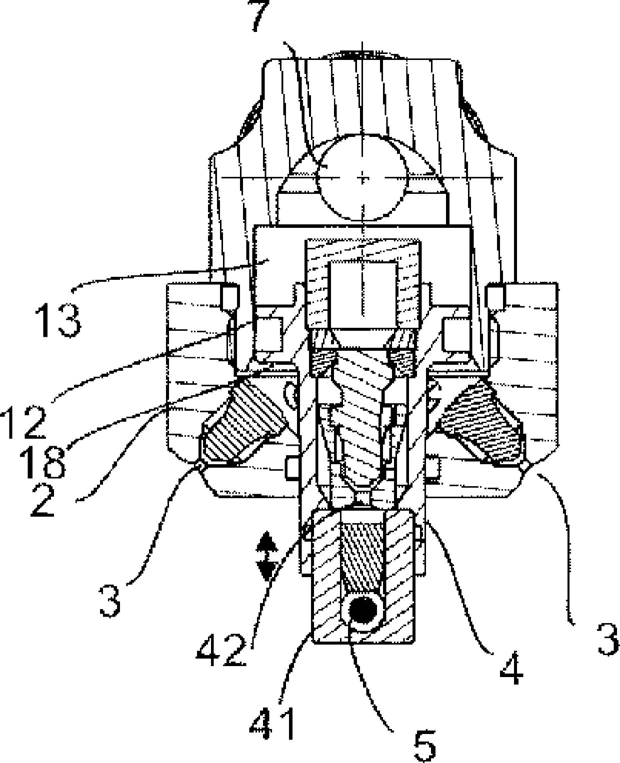
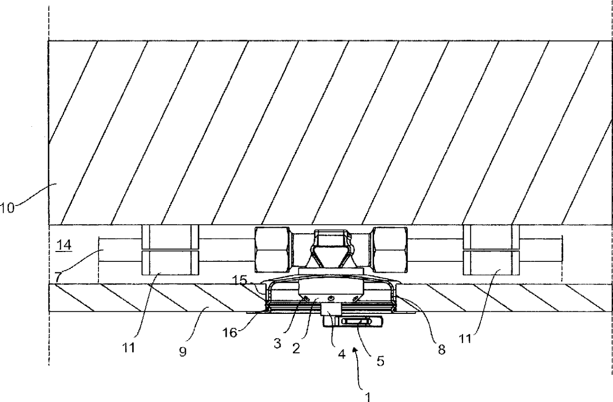
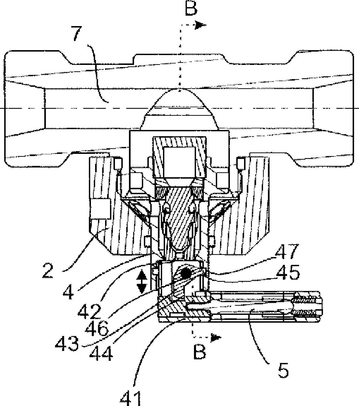
[0015] figure 1 A spray head 1 according to the invention is presented, which is arranged on a fixed surface 10, such as on a ceiling, a wall or a corresponding surface. Lines 7 , or corresponding medium conduits, are provided to the spray head, through which the medium to be sprayed is brought to the spray head. The pipeline is fixed to the fixing surface 10 by fastening means 11 . The wall or ceiling structure comprises a cover plate 9 , such as a suspended ceiling, at a distance from the fixed surface, in which case a space 14 remains between the fixed surface 10 and the cover plate 9 for the pipeline 7 . A hole 15 is formed in the cover plate 9 . A mounting box 8 is arranged in the hole 15, the walls and base of which box extend inwards from the hole 15, ie towards the pipeline 7 in the figure. The protective device 6 is arranged in front of at least one nozzle of the spray head and in front of the trigger element 5 . figure 1 The protective device 6 in the embodiment ...


PUM


Abstract

Spray head, which comprises a spray head body (2), which comprises at least one nozzle (3), a heat-activated triggering element (5), in connection with the spray head of which a protection means (6) is arranged, which protection means is in front of the nozzle (3) in the protective position and mechanically protects the triggering element (5) when the spray head is in a non-active state, and which protection means (6) can be moved to a second position, in which at least one nozzle (3) and the triggering element (5) are not protected by the protection means (6). The triggering element (5) is fitted onto the fixing body (4) of the triggering element, which fixing body can be moved with respect to the spray head body (2) between two positions, a first position in which the spray head is in the non-active state and the fixing body (4) of the triggering element is in the retracted position, and a second position in which the fixing body (4) of the triggering element is pushed out, and which fixing body (4) of the triggering element is arranged to move with respect to the spray head body (2) from the effect of the pressure of the medium from a first position to a second position and at the same time to exert a force on the protection means (6), for moving the protection means from the protective position to a second position, in which case the spray head is placed into a state of readiness in the second position of the fixing body of the triggering element.

Description

technical field [0001] The object of the invention is a spray head as defined in the preamble of claim 1, comprising a spray head body comprising at least one nozzle, a thermally activated trigger element, a protection device being arranged in connection with the spray head of the trigger element, When the spray head is in the inactive state, the protection device is located in front of the nozzles in the protection position and mechanically protects the trigger element, and the protection device can be moved to a second position in which at least one nozzle and trigger elements are not protected by protective devices. Background technique [0002] Such a sprinkler head especially intended for fire extinguishing is known, for example, from the publication EP 1150747 . The nozzle protecting the spray head and the dome of the trigger element can be released by a device movable relative to the holder body. This publication presents an alternative for releasing the dome and so...

Claims


Application Information

Patent Timeline
Patent Type & Authority Applications(China)
IPC IPC(8): A62C37/09A62C31/02
CPCA62C37/09A62C31/02A62C37/08
Inventor H.马蒂拉S.卡约J.赫拉索
Owner MARIOFF CORP OY
Why Eureka
Try Eureka