
Centering device for positioning sheet material in automatic punching line

An automatic line and centering platform technology, applied in the direction of positioning device, feeding device, storage device, etc., can solve the problem of difficult positioning of special-shaped sheet metal, and achieve the goal of overcoming easily damaged sheet metal edges, alleviating impact force, and facilitating automation Effect

Active Publication Date: 2014-04-02
ANHUI JIANGHUAI AUTOMOBILE GRP CORP LTD
View PDF8 Cites 0 Cited by
  • Summary
  • Abstract
  • Description
  • Claims
  • Application Information

AI Technical Summary

Problems solved by technology

[0003] In order to solve the technical problem of difficult positioning of special-shaped sheet metal on the automobile stamping automation line, the invention provides a sheet material positioning centering device for the stamping automation line

Method used


Image

  • Centering device for positioning sheet material in automatic punching line
  • Centering device for positioning sheet material in automatic punching line
  • Centering device for positioning sheet material in automatic punching line

Examples


Embodiment

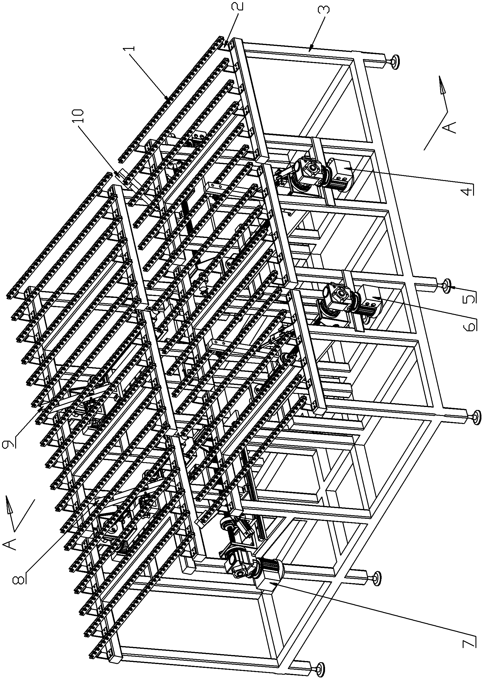
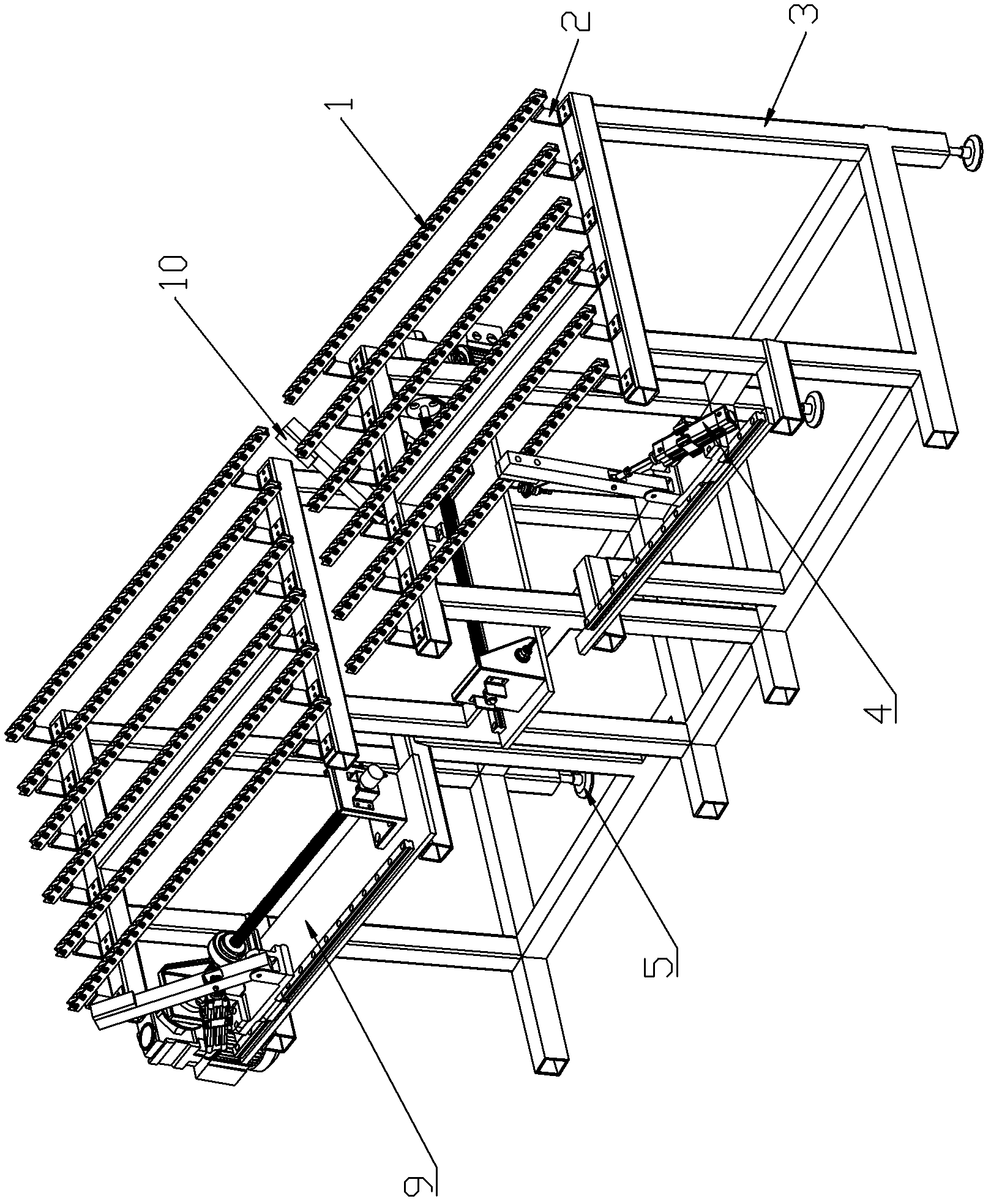
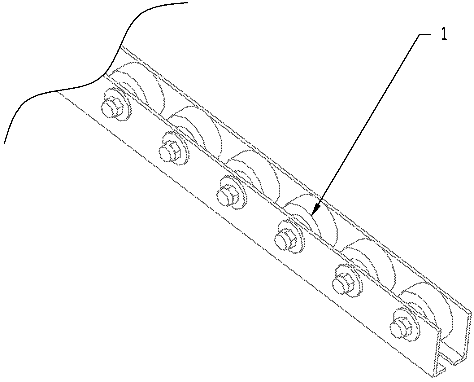
[0022] see figure 1 , the frame 3 used for the sheet metal positioning centering device of the stamping automation line is a cubic frame, and its top surface is slope-shaped, and two rows of roller bars 1 are evenly distributed through the U-shaped bracket 2 along the slope direction of the top of the frame. One row of roller bars is located on the top of the rack, and the other row of roller bars is located on the lower part of the rack top, forming a roller bar slope. The angle between the roller bar slope and the horizontal plane is 7 degrees. The distance between two rows of roller bars is 100mm; the gap between two adjacent roller bars 1 is 100mm; the roller bars include channel steel-shaped roller grooves, and rollers are evenly distributed in the roller grooves, and the rolling direction of the rollers is The direction of the slope at the top of the rack. Adjustment blocks 5 are installed at the bottom of each leg of the frame 3; rotating arm adjustment mechanisms are ...


PUM


Abstract

The invention relates to a centering device for positioning sheet material in an automatic punching line. A top surface of the device frame is in a shape of slope, and uniformly provided with two rows of rollers. Each intermediate part of left and right sides of the frame is provided with a tumbler regulation mechanism. Upper and lower sides of the frame are uniformly provided with two tumbler regulation mechanisms, respectively. A bottom plate of the tumbler regulation mechanism is provided thereon with a lead screw and a guide rail. The lead screw has one end provided with a rotary encoder and the other end connected with a motor reducer. The guide rail is matched with a positioning plate. A lead screw nut, a movable tumbler and a cylinder are arranged on the positioning plate. A connecting rod end of the cylinder is connected with the intermediate and lower part of the movable tumbler. The movable tumblers of the tumbler regulation mechanisms at the left and right sides of the frame are correspondingly arranged in a space between the two rows of rollers. The movable tumblers of the tumbler regulation mechanisms at the upper and lower sides of the frames are correspondingly arranged in the space between the two rows of rollers. The invention solves the problem of difficulty in stable positioning of irregular sheet material; and the beat positioning of the tumbler regulation mechanisms has small impact force, and reduces damage to edges of sheet material.

Description

technical field [0001] The invention belongs to the technical field of action execution of stamping automation equipment, and in particular relates to a plate positioning and centering platform device for stamping automation lines. Background technique [0002] At present, in order to ensure that the robot can accurately and stably grab the sheet and feed it to the stamping equipment every time, a centering device must be installed in front of the material robot on the automotive stamping automation line. The traditional centering device adopts gravity automatic positioning method. The rectangular table of this kind of centering table device has a large inclination angle with the horizontal plane along its diagonal line. Linear stoppers are set up on the two sides of the lower end respectively. Universal rollers are arranged on the table. The self-gravity slides to the lower end, and the two linear stops collide with the edge of the sheet, so that the sheet is positioned. ...

Claims


Application Information

Patent Timeline
Patent Type & Authority Patents(China)
IPC IPC(8): B21D43/00
Inventor 桂方亮严刚崔礼春赵涛
Owner ANHUI JIANGHUAI AUTOMOBILE GRP CORP LTD
Learn More