Construction method of car steel plate spring multi-body model

A leaf spring, multi-body model technology, applied in special data processing applications, instruments, electrical digital data processing, etc., can solve problems such as difficult calculation, complex modeling, and tedious modeling process, and achieve accurate ride comfort simulation.

Active Publication Date: 2012-07-25
CHONGQING CHANGAN AUTOMOBILE CO LTD
View PDF3 Cites 16 Cited by
  • Summary
  • Abstract
  • Description
  • Claims
  • Application Information

AI Technical Summary

Problems solved by technology

[0004] The finite element modal method uses the finite element software to calculate the leaf spring mode, outputs the modal neutral file, and then imports the modal neutral file into the multi-body simulation program, and adds the friction force and contact force between the reeds. The process is The key points and difficulties of this method, there is no better solution for this difficulty
[0005] The principle of the three-segment beam method is to simplify the leaf spring assembly into three sections, and use a function to fit the relationship between the spring force of the leaf spring and its deformation. The model completed by this method is far from the actual structure, and cannot accurately reflect the motion characteristics of the suspension. , the force at the attachment point between the leaf spring and the vehicle body is not accurate enough to guide the design work well
[0006] The principle of the variable cross-section curved beam element method is to discretize the leaf spring into variable cross-section curved beam units. If you want to obtain a more accurate model, you need to discretize the leaf spring into enough units. This method needs to establish each beam unit one by one. The modeling process is cumbersome, and the contact force between the reeds is not easy to establish accurately
[0007] The above methods can better reflect the static stiffness of the leaf spring, but none of them can effectively reflect the dry friction of the leaf spring. Some of them are complex in modeling, some are difficult to calculate, and some cannot be simulated.

Method used


Image

  • Construction method of car steel plate spring multi-body model
  • Construction method of car steel plate spring multi-body model
  • Construction method of car steel plate spring multi-body model

Examples


Embodiment Construction

[0041] The present invention will be described in detail below in conjunction with the embodiments and the accompanying drawings.

[0042] For the specific operation steps and the output results of each step of the construction method of a kind of automobile leaf spring multi-body model described in the present invention, please refer to figure 1 , including the following steps:

[0043] The first step is to test the static stiffness and dynamic force of the leaf spring;

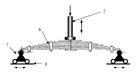
[0044] see figure 2 , support the leaf spring 6 on the guide rail 8 through the support 7, manipulate the static actuator 5 to slowly load, record the load and the deformation of the leaf spring, and test the static stiffness of the leaf spring;

[0045] Load the leaf spring to the design load, and it is in static balance; press 1-15mm, 1-2Hz sine wave to load, and record the deformation and force of the leaf spring;

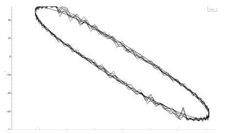
[0046] The second step is to establish a dynamic friction model;

[0047] Model param...


PUM


Abstract

The invention discloses a construction method of a car steel plate spring multi-body model. The construction method comprises the following steps: firstly, testing static stiffness and dynamic force of a steel plate spring; secondly, establishing a dynamic friction model; thirdly, establishing the steel plate spring multi-body model in a multi-body dynamics program; fourthly, adding a dynamic dry friction model to the steel plate spring multi-body model; and fifthly, establishing a suspension system model for simulating a suspension and an entire car. In the construction method, dry friction among steel plate spring reeds is uniformly processed as characteristics of plate spring assembly, and assembly dry friction is described by the dynamic friction model, therefore, dynamic force characteristics of the car steep plate spring can be accurately reflected to reflect the dynamic stiffness formed by the friction, and ride comfort simulation is more accurate.

Description

technical field [0001] The invention relates to a construction method of an automobile suspension dynamics analysis model, in particular to a construction method of a leaf spring multi-body model, which is applied to the analysis of automobile suspension dynamics, vehicle handling stability and ride comfort. Background technique [0002] With the rapid development of CAE technology, the application of automobile suspension dynamics analysis and ride comfort analysis technology is becoming more and more extensive. Leaf spring is one of the most widely used elastic components of automobile suspension. It is often used in front and rear suspensions of trucks, rear suspensions of passenger and cargo vehicles, mini cars, pickup trucks, and off-road vehicles. Therefore, the leaf spring model is established It has an extremely important position in the multi-body modeling of the whole vehicle, and the leaf spring is composed of multiple steel plates, and the dry friction between th...

Claims


Application Information

Patent Timeline
Patent Type & Authority Applications(China)
IPC IPC(8): G06F17/50
Inventor 刘煜李发勇董益亮黄仁祥郑晓勇
Owner CHONGQING CHANGAN AUTOMOBILE CO LTD
Why Eureka
Try Eureka