
Elastic energy storage safety device for tank container

A safety device and container technology, applied in safety belts, life-saving equipment, etc., can solve problems such as poor safety and lack of safety devices, and achieve the effect of easy processing and use, low cost, and guaranteed safety

Active Publication Date: 2012-08-01
哈尔滨建成北方专用车有限公司
View PDF2 Cites 0 Cited by
  • Summary
  • Abstract
  • Description
  • Claims
  • Application Information

AI Technical Summary

Problems solved by technology

[0003] The purpose of the present invention is to solve the problem of poor safety for operators due to the lack of safety devices in the production process of existing large tank containers, and to provide an elastic energy storage safety device for tank containers

Method used


Image

  • Elastic energy storage safety device for tank container
  • Elastic energy storage safety device for tank container
  • Elastic energy storage safety device for tank container

Examples


specific Embodiment approach 1

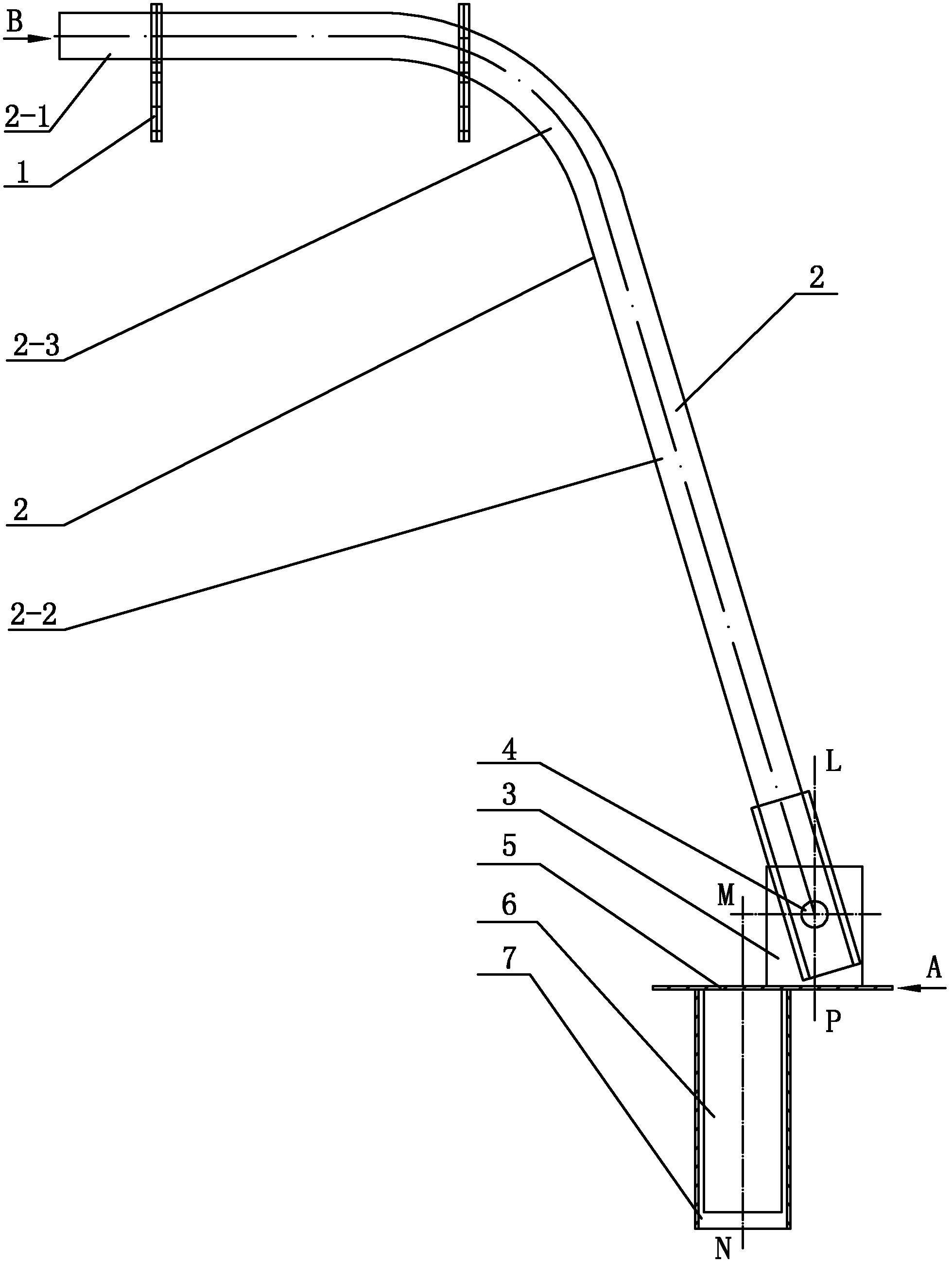
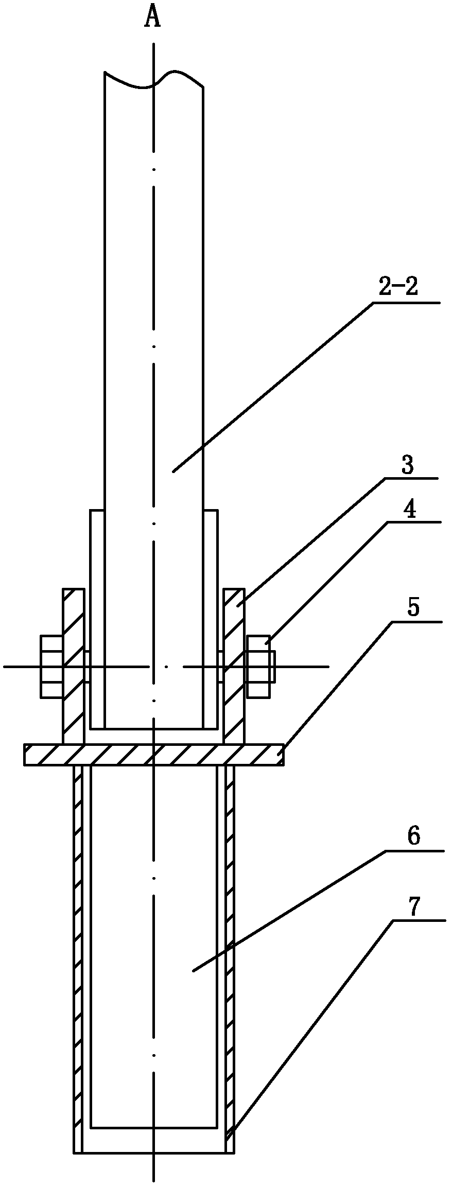
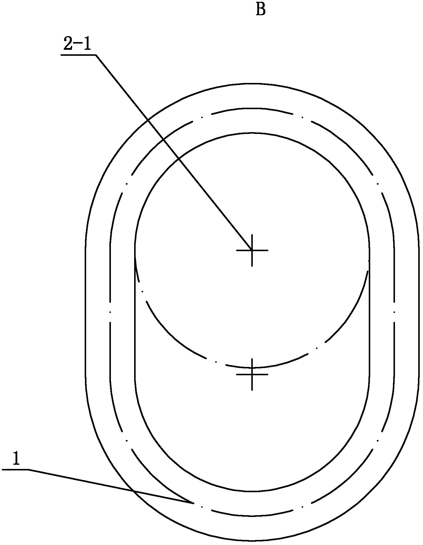
[0007] Specific implementation mode one: combine Figure 1 ~ Figure 3 Describe the present embodiment, the elastic energy storage safety device for the tank container described in the present embodiment includes a suspension ring 1, a connecting rod 2, a cover plate 5, a square pipe 6, a square pipe sleeve 7 and two clips 3, the The connecting rod 2 is an arched connecting rod, and the arched connecting rod is composed of a short rod 2-1, a long rod 2-2 and an arc rod 2-3, and the short rod 2-1 and the long rod 2-2 form Eight-shaped setting, the arc rod 2-3 is arranged between the short rod 2-1 and the long rod 2-2 and the three are made in one piece, the square pipe sleeve 7 is poured in the ground, and the lower end surface of the cover plate 5 is connected with Square pipe 6, square pipe 6 is installed in the square pipe sleeve 7, and two clips 3 are fixed on the upper end surface of cover plate 5 in parallel, and the short rod 2-1 of connecting rod 2 is connected with lift...

specific Embodiment approach 2

[0008] Specific implementation mode two: combination figure 1 To describe this embodiment, the central axis MN of the square pipe 6 in this embodiment is parallel to the straight line LP perpendicular to the center line between the two clips 3 . Set in this way, the central axis of the square tube 6 and the vertical line of the center line between the two clips 3 are not on the same line (not coincident), and the eccentric line can ensure that the square tube 6 and the square tube sleeve 7 do not fall off from the round hole , safe and reliable work. Others are the same as in the first embodiment.

specific Embodiment approach 3

[0009] Specific implementation mode three: combination figure 1 and figure 2 This embodiment is described, the long rod 2 - 2 of the connecting rod 2 of this embodiment is detachably connected to the two clips 3 by bolts 4 . Such setting ensures that the connecting rod 2 cannot move longitudinally, the connection is efficient, and the use is convenient. Others are the same as in the first embodiment.

[0010] work process

[0011] combine Figure 1 ~ Figure 4 To illustrate the working process, a round hole with a diameter of φ100 and a depth of 200 mm is drilled on the ground at a distance of 2500 mm from the center line of the rotating tire 8; the square pipe sleeve 7 is poured into the round hole and fixed, and the lower end surface of the cover plate 5 is fixedly connected to the square pipe 6 , the square pipe 6 is put into the square pipe sleeve 7, the upper part of the large-scale tank-type container body 9 is welded by the suspension ring 1 and the connecting rod 2...


PUM


Abstract

The invention discloses an elastic energy storage safety device for a tank container, which relates to a safety device for a tank container and is used for solving the problem of poor safety during working of operating personnel caused by lacking of a safety device in the production process of a large-sized tank container. The safety device comprises a hoisting ring, a connecting rod, a cover plate, a square pipe, a square pipe sleeve and two clamping pieces, wherein the connecting rod is an arch-shaped connecting rod; the arch-shaped connecting rod consists of a short rod, a long rod and a circular arc rod; the short rod and the long rod are arranged in an inverted V form; the circular arc rod is arranged between the short rod and the long rod; the circular arc rod, the short rod and the long rod are made integrally; the square pipe sleeve is poured into the ground; the lower end face of the cover plate is connected with the square pipe; the square pipe is arranged in the square pipe sleeve; the two clamping pieces are fixed in parallel on the upper end face of the cover plate; the short rod of the connecting rod is connected with the hoisting ring; the other end of the long rod of the connecting rod is arranged between two clamping pieces which are arranged in parallel; and the long rod of the connecting rod is detachably connected with the two clamping pieces. The elastic energy storage safety device can be used in the production process of large-sized tank containers.

Description

technical field [0001] The invention relates to a safety device for tank containers. Background technique [0002] During the production process of large-scale tank containers, operators need to work on the upper part of the tank body. Generally, there is no place to install safety belt rings above the tank body. Contents of the invention [0003] The purpose of the present invention is to solve the problem of poor safety for operators due to the lack of safety devices in the production process of existing large tank containers, and further provide an elastic energy storage type safety device for tank containers. [0004] The technical solution adopted by the present invention to solve the above problems is: the elastic energy storage type safety device for the tank container of the present invention includes a suspension ring, a connecting rod, a cover plate, a square pipe, a square pipe sleeve and two clips. The rod is an arched connecting rod. The arched connecting rod...

Claims


Application Information

Patent Timeline
Patent Type & Authority Applications(China)
IPC IPC(8): A62B35/00
Inventor 马殿武唐旭东王敏张杰曹国斌
Owner 哈尔滨建成北方专用车有限公司
Learn More