Elastic energy storage safety device for tank container
A safety device and container technology, which is applied to safety belts, life-saving equipment and other directions, can solve the problems of lack of safety devices and poor safety, and achieve the effects of low cost, easy processing and use, and protection of operators.
- Summary
- Abstract
- Description
- Claims
- Application Information
AI Technical Summary
Problems solved by technology
Method used
Image
Examples
specific Embodiment approach 1
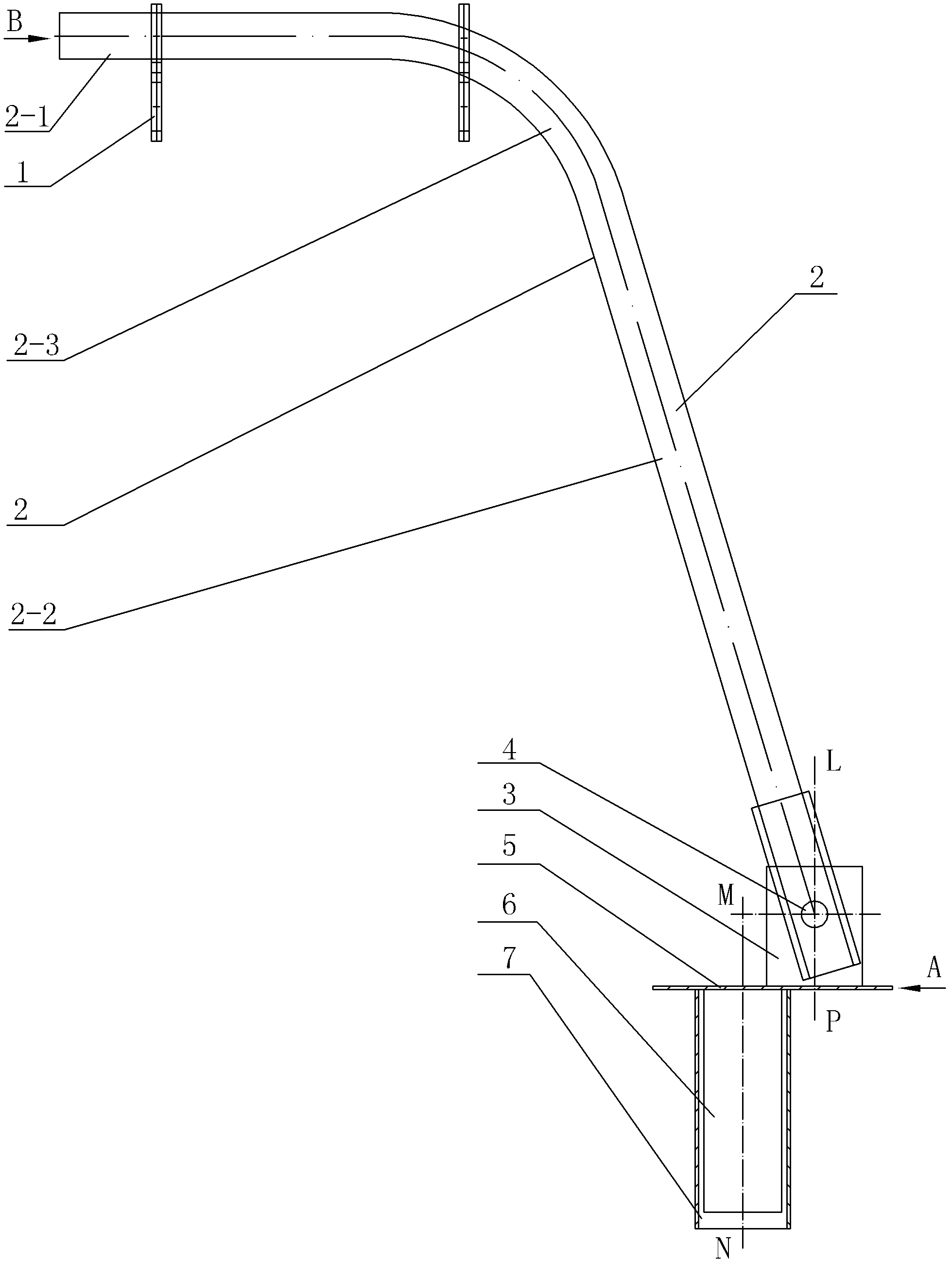
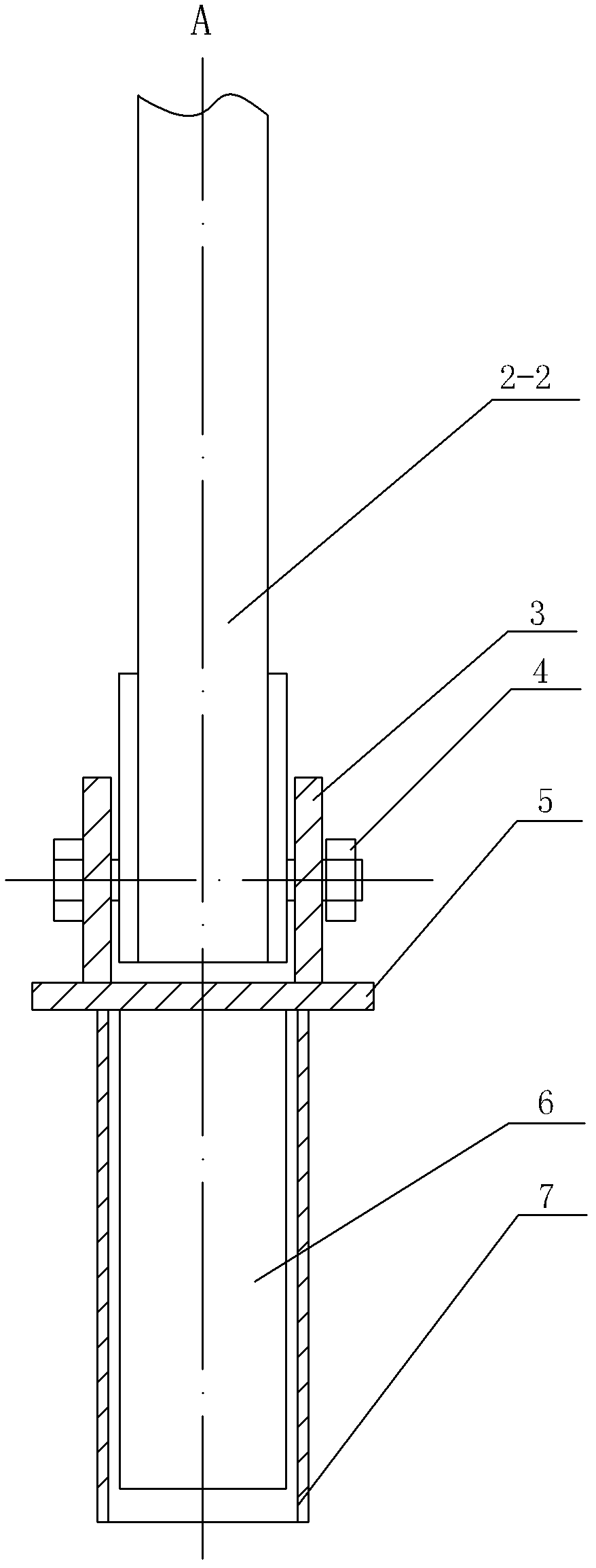
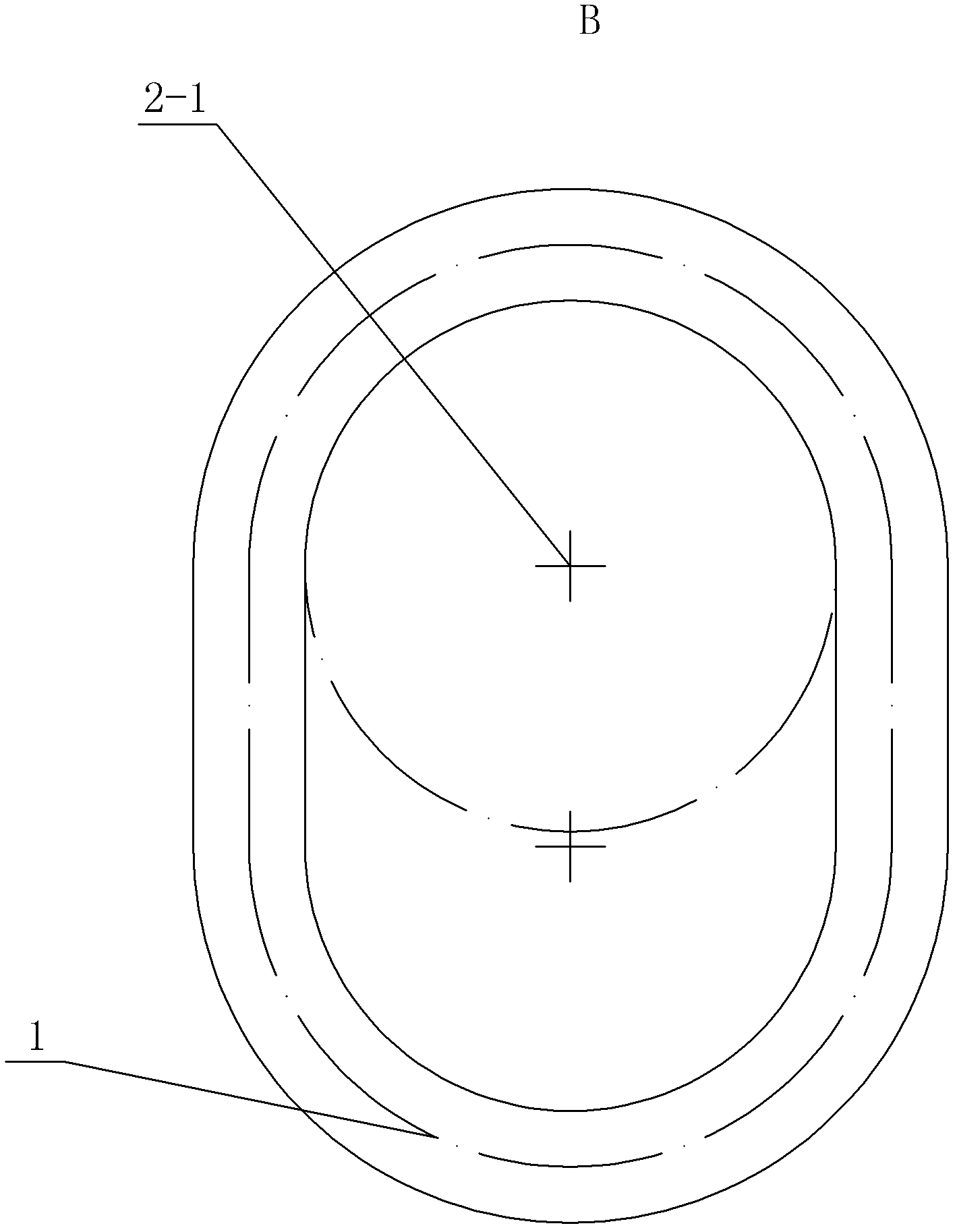
[0007] Specific implementation mode one: combine Figure 1 ~ Figure 3 Describe the present embodiment, the elastic energy storage safety device for the tank container described in the present embodiment includes a suspension ring 1, a connecting rod 2, a cover plate 5, a square pipe 6, a square pipe sleeve 7 and two clips 3, the The connecting rod 2 is an arched connecting rod, and the arched connecting rod is composed of a short rod 2-1, a long rod 2-2 and an arc rod 2-3, and the short rod 2-1 and the long rod 2-2 form Eight-shaped setting, the arc rod 2-3 is arranged between the short rod 2-1 and the long rod 2-2 and the three are made in one piece, the square pipe sleeve 7 is poured in the ground, and the lower end surface of the cover plate 5 is connected with Square pipe 6, square pipe 6 is installed in the square pipe sleeve 7, and two clips 3 are fixed on the upper end surface of cover plate 5 in parallel, and the short rod 2-1 of connecting rod 2 is connected with lift...
specific Embodiment approach 2
[0008] Specific implementation mode two: combination figure 1 To describe this embodiment, the central axis MN of the square pipe 6 in this embodiment is parallel to the straight line LP perpendicular to the center line between the two clips 3 . In this way, the central axis of the square tube 6 and the vertical line of the center line between the two clips 3 are not on the same line (not coincident), and the eccentric line can ensure that the square tube 6 and the square tube sleeve 7 do not fall out of the round hole , safe and reliable work. Others are the same as in the first embodiment.
specific Embodiment approach 3
[0009] Specific implementation mode three: combination figure 1 and figure 2 This embodiment is described, the long rod 2 - 2 of the connecting rod 2 of this embodiment is detachably connected to the two clips 3 by bolts 4 . Such setting ensures that the connecting rod 2 cannot move longitudinally, the connection is efficient, and the use is convenient. Others are the same as in the first embodiment.
[0010] work process
[0011] combine Figure 1 ~ Figure 4 To illustrate the working process, a round hole with a diameter of φ100 and a depth of 200 mm is drilled on the ground at a distance of 2500 mm from the center line of the rotating tire 8; the square pipe sleeve 7 is poured into the round hole and fixed, and the lower end surface of the cover plate 5 is fixedly connected to the square pipe 6 , the square pipe 6 is put into the square pipe sleeve 7, the upper part of the large-scale tank-type container body 9 is welded by the suspension ring 1 and the connecting rod 2...
PUM
 Abstract
Description
Claims
Application Information
 - R&D
- Intellectual Property
- Life Sciences
- Materials
- Tech Scout
- Unparalleled Data Quality
- Higher Quality Content
- 60% Fewer Hallucinations
Browse by: Latest US Patents, China's latest patents, Technical Efficacy Thesaurus, Application Domain, Technology Topic, Popular Technical Reports.
© 2025 PatSnap. All rights reserved.Legal|Privacy policy|Modern Slavery Act Transparency Statement|Sitemap|About US| Contact US: help@patsnap.com


