System and method for adjusting vehicle light

A lighting adjustment and vehicle technology, which is applied to vehicle components, optical signals, signal devices, etc., can solve problems such as hidden dangers of safe driving, and achieve the effect of ensuring safe driving

Active Publication Date: 2012-08-01
BEIJING JINGWEI HIRAIN TECH CO INC
View PDF7 Cites 16 Cited by
  • Summary
  • Abstract
  • Description
  • Claims
  • Application Information

AI Technical Summary

Problems solved by technology

[0004] In view of this, the embodiment of the present application provides a vehicle lighting adjustment system and method to solve the problem that the existing vehicle headlights can only be used

Method used


Image

  • System and method for adjusting vehicle light
  • System and method for adjusting vehicle light
  • System and method for adjusting vehicle light

Examples


Example Embodiment

[0067] Embodiment one:

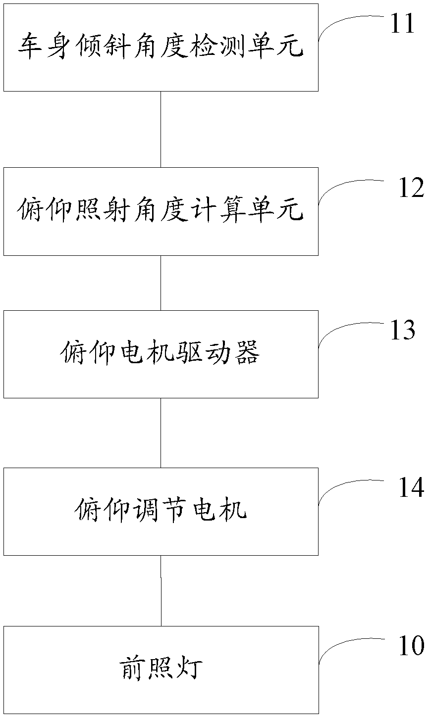
[0068] The present application discloses a vehicle lighting adjustment system. A pitch adjustment axis (not shown in the figure) for adjusting the pitch irradiation angle of the headlight is provided on the headlight of the vehicle. figure 1 It is a schematic structural diagram of a system for adjusting the tilting angle of illumination of vehicle lights disclosed in the embodiment of the present application.

[0069] like figure 1 As shown, 10 in the figure is a headlight, and the system includes: a vehicle body tilt angle detection unit 11 , a pitch illumination angle calculation unit 12 , a pitch motor driver 13 and a pitch adjustment motor 14 .

[0070] The vehicle body tilt angle detection unit 11 is used to detect the vehicle body tilt angle.

[0071] In the embodiment of the present application, the detection of the inclination angle of the vehicle body is realized by detecting the distance between the front part of the vehicle body and the gr...

Example Embodiment

[0079] Embodiment two:

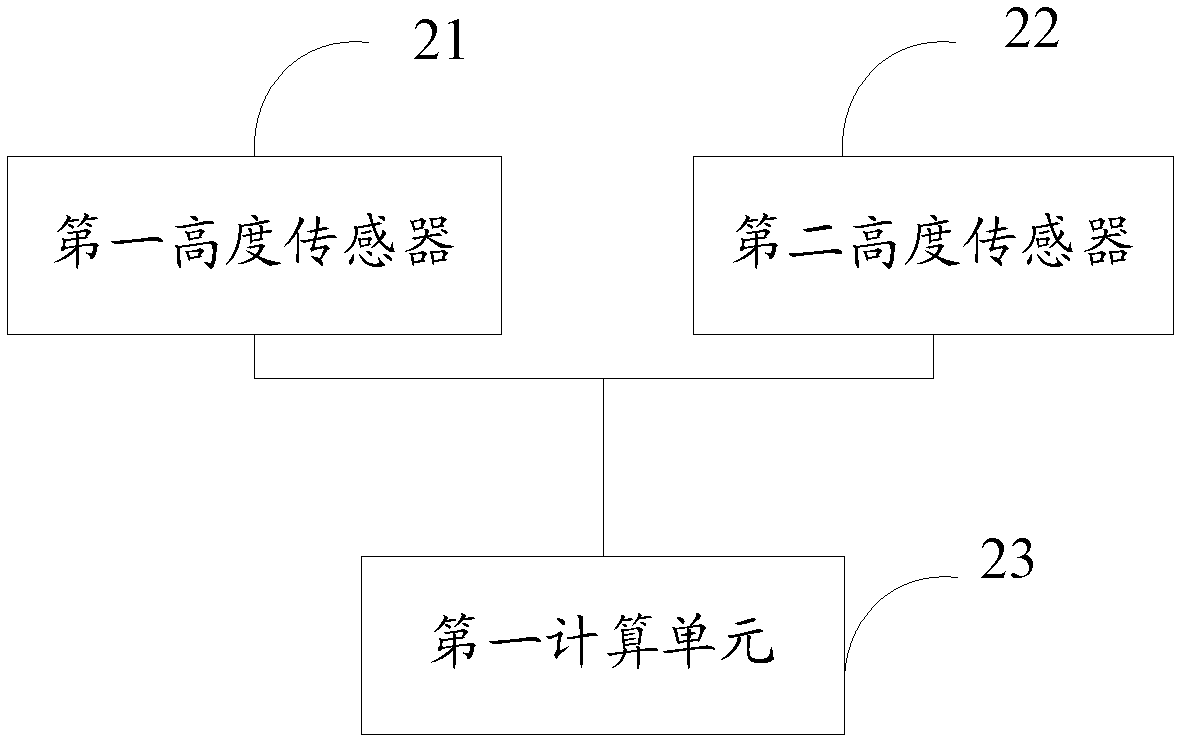
[0080] In the embodiment of the present application, the vehicle body inclination angle detection unit adopts a height sensor as an example for illustration.

[0081] like figure 2 As shown, the vehicle body tilt angle detection unit may include: a first height sensor 21 , a second height sensor 22 and a first calculation unit 23 .

[0082] The first height sensor 21 is used to measure the height of the front part of the vehicle body; the second height sensor 22 is used to measure the height of the rear part of the vehicle body. The first height sensor 21 and the second height sensor 22 are respectively mounted on the front part of the vehicle body and the rear part of the vehicle body, and the heights measured are the height of the front part of the vehicle body from the ground and the height of the rear part of the vehicle body from the ground.

[0083] The first calculating unit 23 is used for calculating the tilt angle of the vehicle body accord...

Example Embodiment

[0089] Embodiment three:

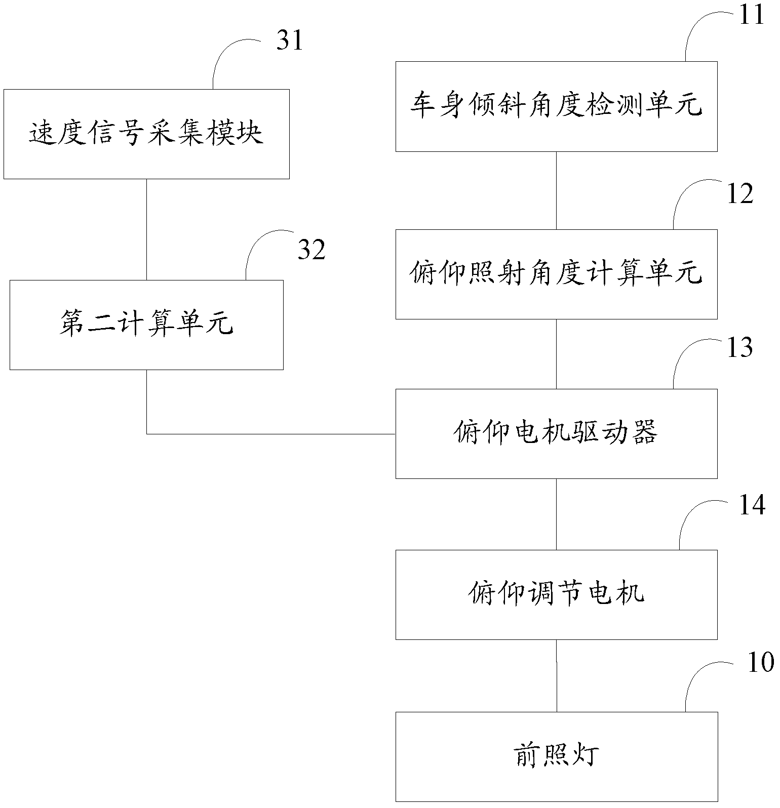
[0090] The above-mentioned embodiment mainly describes the adjustment of the pitching irradiation angle due to the change of the tilt angle of the vehicle body. When driving on a straight road, the tilt angle of the vehicle body will remain unchanged at this time. In this case, according to Depending on the speed of the vehicle, the distance in front of the vehicle that the driver needs to observe is different. For example, when the vehicle speed is higher, the longer the irradiation distance is required. Conditions for safe driving.

[0091] Therefore, the embodiment of the present application, on the basis of the first embodiment, also provides a headlamp tilting irradiation angle adjustment system that takes the vehicle speed into account, so as to realize that the irradiation angle of the headlamp can be adjusted according to different vehicle speeds. .

[0092] In the embodiment of this application, as image 3 As shown, the system also inclu...


PUM


Abstract

The invention discloses a system and a method for adjusting the vehicle light. A pitch adjusting shaft for adjusting the pitch irradiation angle of a headlamp is arranged on the headlamp of the vehicle, so that the problems that twp preset irradiation angles of a traditional vehicle headlamp in the driving process cannot meet the requirement under the condition that road conditions are complex and cause great potential hazards. The system comprises a vehicle body inclined angle detecting unit, a pitch irradiating angle calculating unit, a pitch motor driver and a pitch adjusting motor. The method comprises the following steps: detecting the inclined angle of the vehicle body by using the vehicle body inclined angle detecting unit; calculating the pitch irradiation angle by using the pitch irradiation angle calculating unit; converting the pitch irradiation angle into a pitch driving instruction and transmitting the pitch driving instruction to the pitch adjusting motor by using the pitch motor driver; and adjusting the pitch adjusting shaft connected with the pitch adjusting motor according to the pitch driving instruction to enable the vehicle headlamp to be always kept at the optimal irradiation angle, thereby solving the problems.

Description

technical field [0001] The present application relates to the technical field of vehicle light adjustment, in particular to a vehicle light adjustment system and method. Background technique [0002] At present, vehicle headlights include two modes of high beam illumination and low beam illumination. Through prior adjustment, the high beam illumination can correspond to a preset headlight irradiation angle, and the low beam illumination can correspond to another preset headlight illumination. Irradiation angle. During the driving process of the vehicle, the driver subjectively judges the preset angle corresponding to the high beam irradiation or the preset angle corresponding to the low beam irradiation according to the changes in the vehicle load conditions, road conditions, driving conditions and weather conditions, and then manually controls the The high and low light switching device performs a corresponding switching operation to realize the adjustment of the irradiati...

Claims


Application Information

Patent Timeline
IPC IPC(8): B60Q1/115
Inventor 李波李晨陈筱婧蔡绍晓
Owner BEIJING JINGWEI HIRAIN TECH CO INC
Why Eureka
Try Eureka