Light guide structure, backlight module and manufacturing method thereof

A manufacturing method and a backlight module technology are applied to the light guide plate structure, the backlight module and the manufacturing field thereof, and can solve the problems of low luminous efficiency, poor uniformity of white light emission, and difficult control of the uniformity of phosphor powder distribution, and achieve the effect of avoiding moisture.

Inactive Publication Date: 2012-08-08
AU OPTRONICS CORP
View PDF4 Cites 71 Cited by
  • Summary
  • Abstract
  • Description
  • Claims
  • Application Information

AI Technical Summary

Problems solved by technology

However, since the package body of the light emitting diode is usually dripped onto the light emitting diode chip by dispensing and cured by heating, its surface is mostly an arc-shaped curved surface, which makes it difficult to control the uniformity of phosphor powder distribution in the p

Method used


Image

  • Light guide structure, backlight module and manufacturing method thereof
  • Light guide structure, backlight module and manufacturing method thereof
  • Light guide structure, backlight module and manufacturing method thereof

Examples


Embodiment Construction

[0055] The present invention will be described in detail below in conjunction with the accompanying drawings and specific embodiments, but not as a limitation of the present invention.

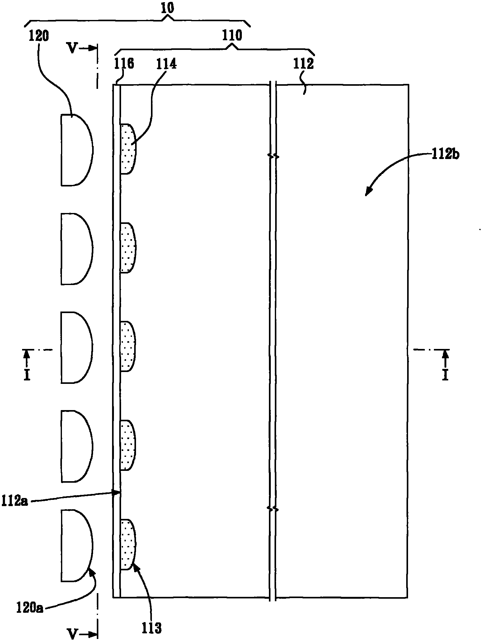
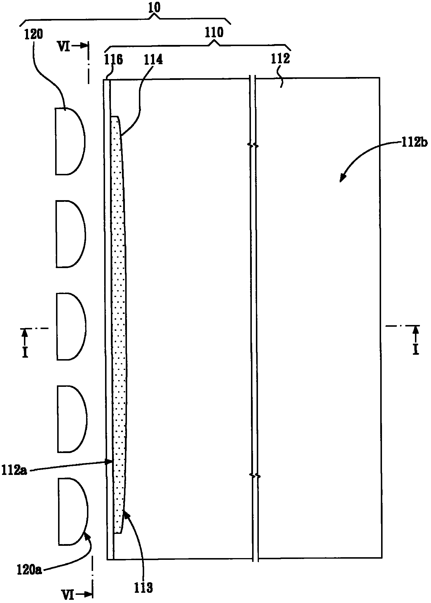
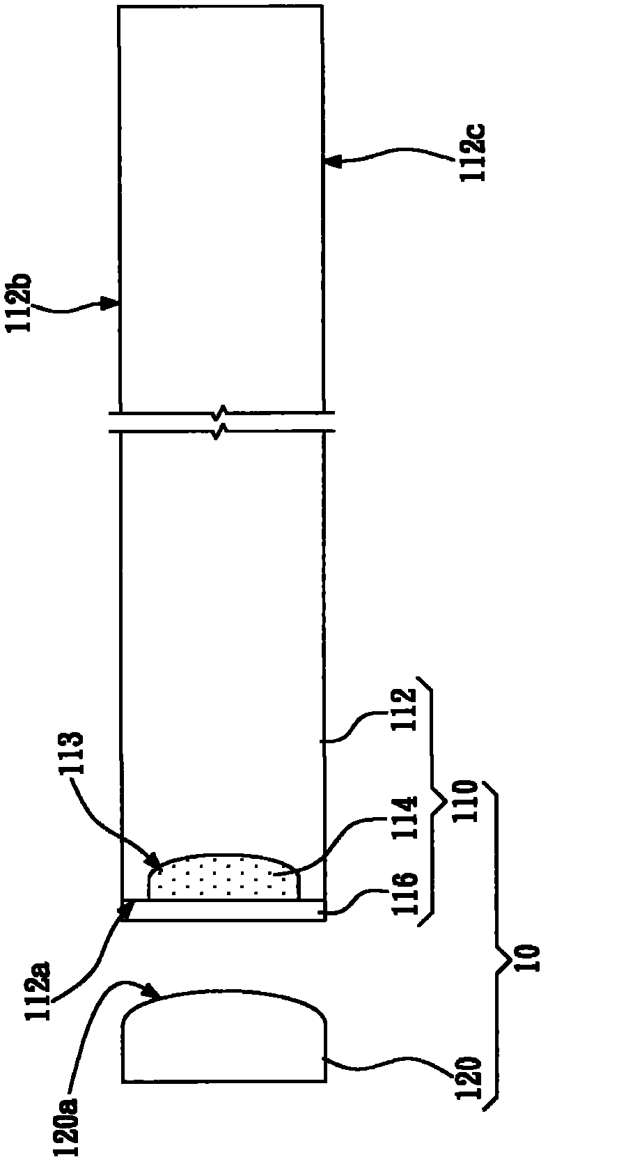
[0056] figure 1 It is a top view of the backlight module according to the first embodiment of the present invention. figure 2 It is a top view of the backlight module according to the second embodiment of the present invention. and image 3 for figure 1 and 2 Sectional view of the median line I-I. Figure 4 is a top view of a backlight module according to a third embodiment of the present invention, and Figure 5 for Figure 4 Sectional view of the median line II-II. Figure 6 is a bottom view of a backlight module according to a fourth embodiment of the present invention, and Figure 7 for Figure 6 Sectional view of the median line III-III.

[0057] refer to Figures 1 to 7 , the backlight module 10 includes a light guide plate structure 110 and at least one light source 120 .

...


PUM


Abstract

The invention provides a light guide structure, a backlight module and a manufacturing method thereof. The light guide structure includes a light guide plate, an optical converting element and an optical vapor barrier. The light guide plate is provided with a light receiving face. The chemical vapor barrier covers the light receiving face. The optical converting element is arranged on the light receiving face and between the light guide plate and the optical vapor barrier. The invention utilizes the optical vapor barrier to separate optical converting element and the external world, thereby preventing the optical converting element from being affected with damp. Thus, the reduction of the optical converting efficiency is decelerated.

Description

technical field [0001] The present invention relates to a backlight module, in particular to a light guide plate structure, a backlight module and a manufacturing method thereof. Background technique [0002] Liquid crystal display devices have been widely used in electronic products such as personal digital assistants, notebook computers, digital cameras, mobile phones, and liquid crystal televisions. However, since the liquid crystal display device is not self-illuminating, it needs a backlight module to have a display function. [0003] The liquid crystal display device is mainly composed of a liquid crystal panel and a backlight module. The liquid crystal panel mainly includes two transparent substrates and a liquid crystal layer, and the liquid crystal layer is disposed between the two transparent substrates. The light emitting surface of the backlight module faces the liquid crystal layer to provide the surface light source required by the liquid crystal panel, so th...

Claims


Application Information

Patent Timeline
IPC IPC(8): F21V8/00F21S8/00G02F1/13357F21Y101/02F21Y115/10
Inventor 庄幸蓉范富诚
Owner AU OPTRONICS CORP
Why Eureka
Try Eureka