Automatic bending device for heat pipe

A bending device and heat pipe technology, applied in the field of machinery, can solve problems such as inconsistent bending effects, affecting production efficiency, and substandard arcs, so as to achieve good bending effects, avoid bending quality differences, and improve efficiency

Inactive Publication Date: 2012-08-15
FURUKAWA AVC ELECTRONICS (SUZHOU) CO LTD
View PDF5 Cites 15 Cited by
  • Summary
  • Abstract
  • Description
  • Claims
  • Application Information

AI Technical Summary

Problems solved by technology

At present, bending fixtures are generally used in the industry for manual bending. However, due to the different bending strength and experience of operators, the bendi

Method used


Image

  • Automatic bending device for heat pipe
  • Automatic bending device for heat pipe
  • Automatic bending device for heat pipe

Examples


Example Embodiment

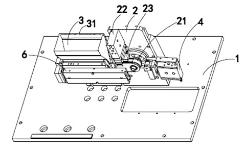
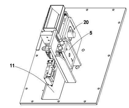
[0017] The invention discloses an automatic bending device for heat pipes, such as figure 1 , figure 2 As shown, it includes a frame 1, on which a platen 2 is vertically fixed, a vibrating machine 20 is arranged on one side of the platen 2, and one end of the vibrating machine 20 passes through the platen 2 to connect with a In the barrel 3 where the heat pipe to be bent is placed, the barrel 3 is provided with a scribe line 31, and the barrel 3 is an adjustable barrel that can be adjusted according to the specifications and the scribe line of the heat pipe.

[0018] A feeding mechanism 6 is provided under the barrel 3. Specifically, the feeding mechanism 6 is arranged below the material opening of the barrel 3. The feeding mechanism 6 is fixed on the frame 1, and the bending device further includes a fixed block 21 and a rotating mechanism 5 that drives the fixed block 21 to rotate. The rotating mechanism 5 and the vibrating machine 20 are arranged on the same side of the plate...


PUM


Abstract

The invention provides an automatic bending device for a heat pipe. The automatic bending device comprises a frame, wherein a bedplate is vertically fixed on the frame; a shaking machine is arranged at one side of the bedplate; the shaking machine is connected with a charging barrel for arranging the heat pipe through the bedplate; a feeding mechanism for conveying the heat pipe is arranged under the charging barrel; the feeding mechanism is fixed on a table board; the bending device also comprises a fixed block and a rotating mechanism for driving the fixed block to rotate; a rotating shaft of the rotating mechanism is connected with the fixed block; the rotating mechanism and the shaking machine are arranged at the same side of the bedplate; a fixed block pressing mechanism is arranged on the fixed block; a movable block pressing mechanism is arranged in front of the fixed block; a gap is arranged between the movable block pressing mechanism and the fixed block; the movable block pressing mechanism presses an end to be bent of the heat pipe downwards; a blanking opening is arranged on the frame, and the blanking opening is arranged under the gap. According to the invention, the heat pipe can be automatically bent, the difference of bending quality completely caused by manual work is avoided and the bending effect is good. Two heat pipes are bent once, and continuous operation can be carried out, time and labor are saved, and the efficiency is greatly improved.

Description

technical field [0001] The invention relates to an automatic bending device, in particular to an automatic bending device for heat pipes, and belongs to the field of mechanical technology. Background technique [0002] Heat pipes are currently widely used heat exchange elements, and their thin-walled pipe bodies are usually bent into a certain arc. At present, bending fixtures are generally used in the industry for manual bending. However, due to the different bending strength and experience of operators, the bending quality is often not high, the arc is not up to standard, the bending effect is not uniform, and it is laborious and time-consuming. , affecting production efficiency. Contents of the invention [0003] The purpose of the present invention is to solve the above-mentioned technical problems, and to provide an automatic bending device for heat pipes. [0004] The purpose of the present invention is achieved through the following technical solutions: [0005] ...

Claims


Application Information

Patent Timeline
IPC IPC(8): B21D7/024B21D7/12B21D43/02B21D7/16
Inventor 孙文聪
Owner FURUKAWA AVC ELECTRONICS (SUZHOU) CO LTD
Why Eureka
Try Eureka