Pneumatic tire

A pneumatic tire, tire circumferential technology, applied in tire components, tire tread/tread pattern, rolling resistance optimization, etc., to achieve good rolling resistance and wet performance, suppress passing sound, maintain rolling resistance and wet performance Effect

Active Publication Date: 2012-08-15
YOKOHAMA RUBBER CO LTD
View PDF7 Cites 9 Cited by
  • Summary
  • Abstract
  • Description
  • Claims
  • Application Information

AI Technical Summary

Problems solved by technology

Contents of

Method used


Image

  • Pneumatic tire
  • Pneumatic tire
  • Pneumatic tire

Examples


Example Embodiment

[0038] example

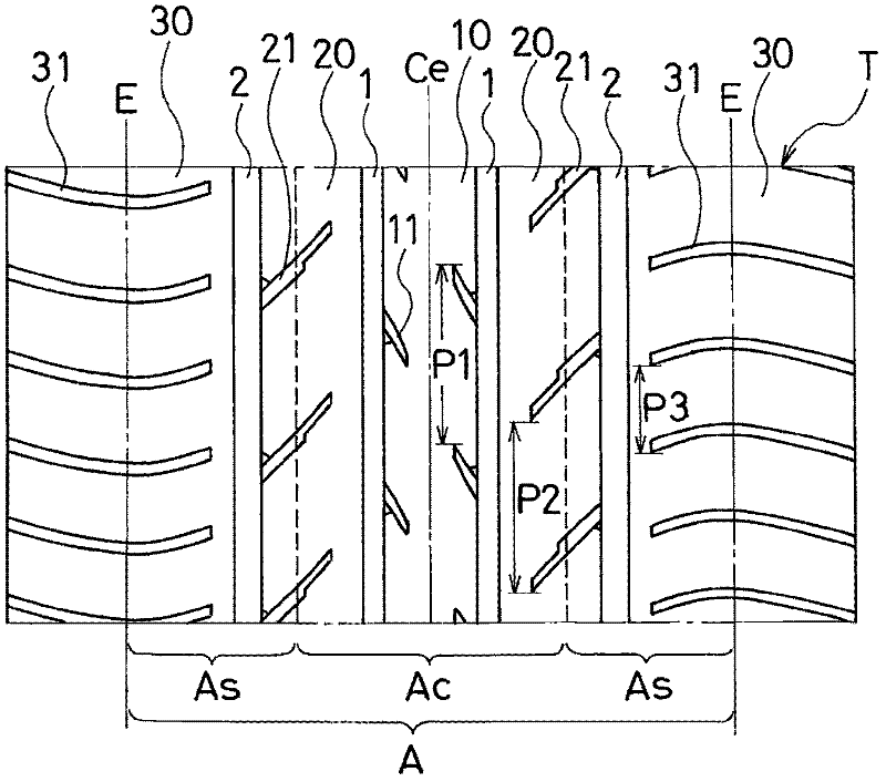
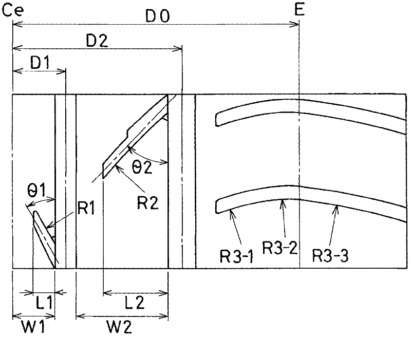
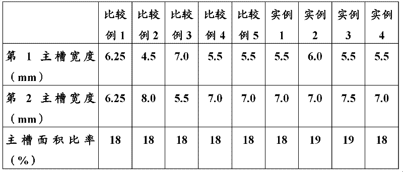
[0039] Pneumatic tires of Comparative Examples 1 to 5 and Examples 1 to 4 were produced. The tire size was 195 / 65R1591H, and the tread portion was provided with a pair of first main grooves located on both sides of the center position and extending in the tire circumferential direction, and a pair of first main grooves located on both sides of the center position. The first main groove is closer to the shoulder side and is a pair of second main grooves extending in the tire circumferential direction. A central rib is divided between the pair of first main grooves. The middle rib is divided between the two, and the shoulder rib is divided on the outer side of the second main groove, wherein a plurality of grooves are respectively formed on the central rib, the middle rib and the shoulder rib. The structure of the grooves varies.

[0040] The tires of Comparative Examples 1 to 4 and Examples 1 to 4 are as follows figure 1 As shown, on the central rib pattern a...


PUM


Abstract

The present invention provides a tire which is provided with central side main grooves (1,1) and tire shoulder side main grooves (2,2) at a tire surface part T. Central strip-shaped patterns (10) are curved between the main grooves (1,1), and central strip-shaped patterns (20) are curved between the main grooves (1,2), wherein, on the central strip-shaped patterns (10) and the central strip-shaped patterns (20), a plurality of tread grooves (11,21) which are terminated in the strip-shaped patterns are formed according to a mode that the groove width reduces gradually in a process of approaching the central side. The distance between the central position of the tire surface part (T) and the center of the main groove (1) is set to 15%-25% of the distance between the central position and a grounding end. The distance between the central position of the tire surface part (T) and the main groove (2) is set to 60%-80% of the distance between the central position and the grounding end. The width of the main groove (1) is set to 70%-90% of the width of the main groove (2). The total area of the main groove (1) and the main groove (2) is set to 15%-25% of the area of the grounding area (A) in the tire surface part (T). The groove area ratio of a central area (Ac) is set to be smaller than that of a tire shoulder area (As).

Description

technical field [0001] The present invention relates to a pneumatic tire provided with four main grooves extending in the tire circumferential direction on the tread portion, and more specifically, to a pneumatic tire capable of reducing passing noise while maintaining good rolling resistance and wet performance . Background technique [0002] When a vehicle passes by, the pneumatic tires installed on the vehicle will generate noise, which is generally called passing sound. The passing sound is amplified by the suction effect when the air in the grooves of the tread portion is compressed and released. Therefore, reducing the groove area of ​​the tread portion is effective for reducing the passing sound. For example, in a pneumatic tire in which four main grooves extending in the tire circumferential direction are provided on the tread portion (for example, refer to Patent Document 1), the passage sound can be reduced by reducing the groove area of ​​the tread portion. [...

Claims


Application Information

Patent Timeline
IPC IPC(8): B60C11/03B60C11/117
CPCB60C11/01B60C11/03B60C11/0306B60C2011/0381B60C11/13B60C11/04B60C2011/0395B60C2011/0372Y02T10/86
Inventor 井上晴隆
Owner YOKOHAMA RUBBER CO LTD
Why Eureka
Try Eureka