

Tripod head
A technology of tripod head and body, which is applied in the field of hydraulic damping devices and damping devices, and can solve the problems that it is impossible to set zero damping force, the damping elements cannot be completely separated from each other, and the structure is complicated.
- Summary
- Abstract
- Description
- Claims
- Application Information
AI Technical Summary
Problems solved by technology
Method used
Image

Examples
Embodiment Construction
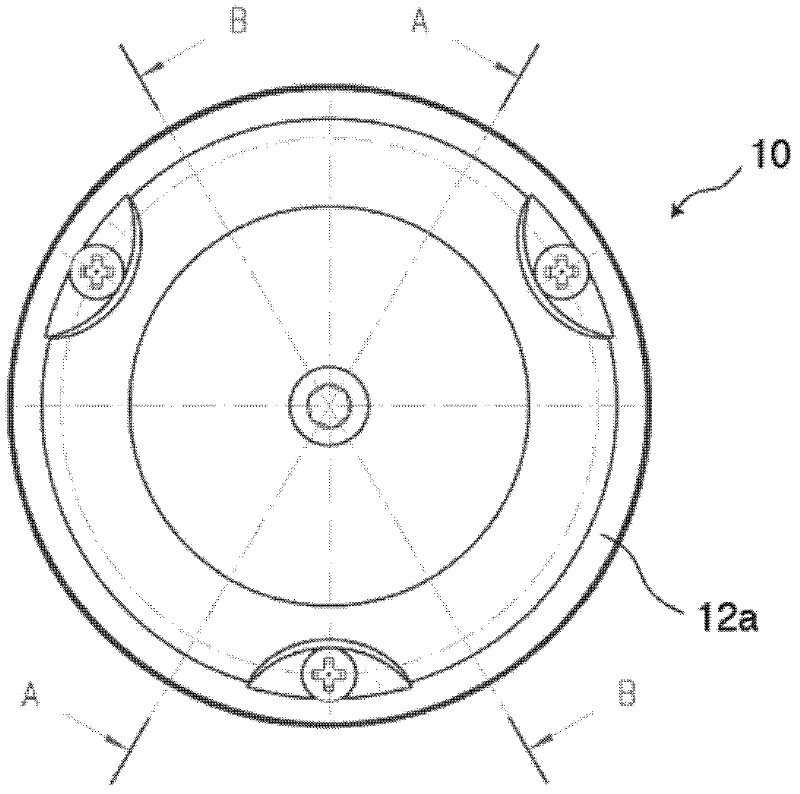
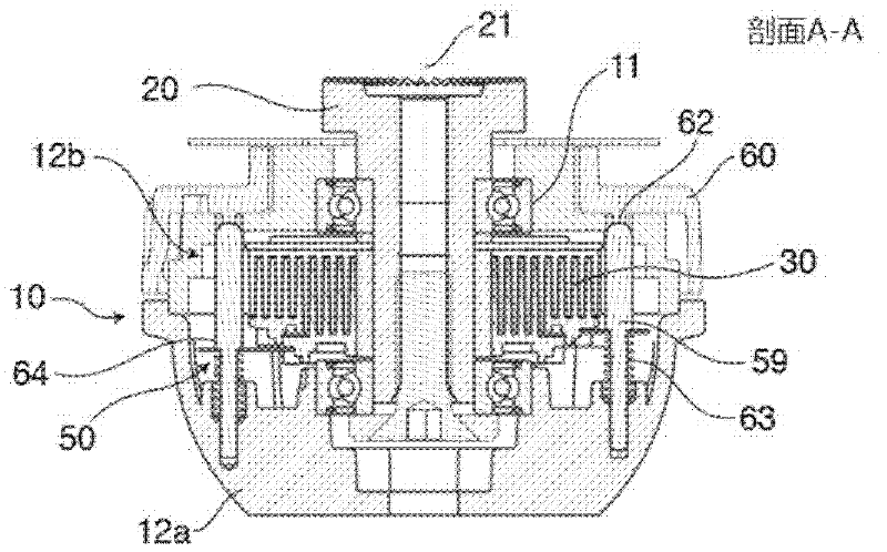
[0025] figure 1 A partial top view of the tripod head of the present invention is given. figure 2 and image 3Shown in is the base body 10 (second body), the shaft 20 (first body) is rotatably installed in the base body 10 through the bearing 11, and is connected with the intermediate body of the tripod head not shown in the figure. The shaft 20 is rotatable about a pivot 21 relative to the base body 10, which is usually fixed on a tripod. The base body 10 in the illustrated embodiment comprises two half shells 12a, 12b.
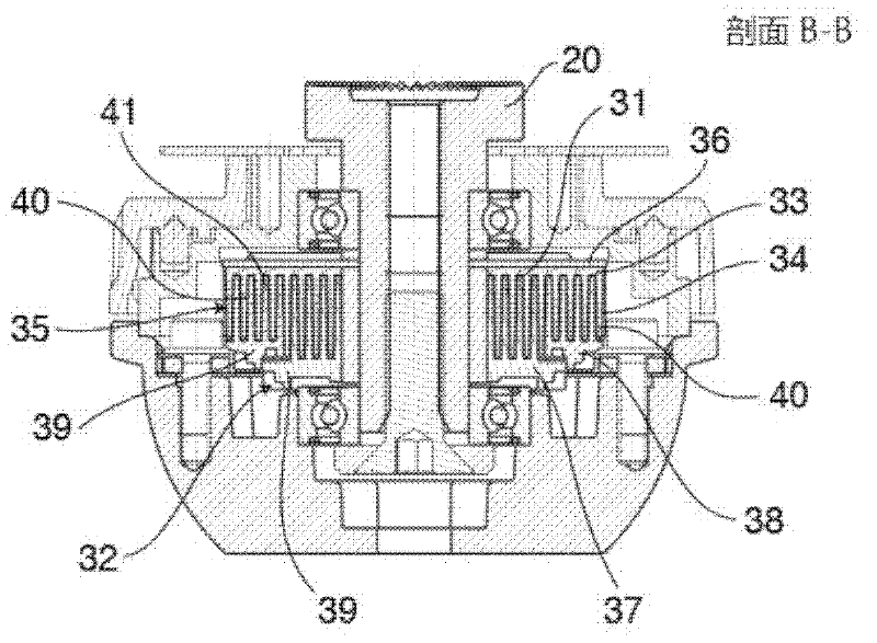
[0026] In order to be able to damp the rotational movement of the shaft 20 relative to the base body 10 , a damping device 30 is provided. The damping device mainly includes a first damping element 31 and a second damping element 32 .
[0027] The first damping element 31 has an annular chassis 33 coaxial with the pivot 21 . Several concentrically arranged annular ribs 34 extend from the chassis 33 along the axis (along the direction of the pivot 21 )....
PUM
 Abstract
Description
Claims
Application Information