Cylindrical electronic permanent-magnet spring with dual effects

A two-way acting, electro-permanent magnet technology, applied in the direction of magnetic springs, springs, springs/shock absorbers, etc., can solve problems such as poor control of deformation and performance impact, and achieve good prospects for use and adjustable damping force

Pending Publication Date: 2020-02-07
JINLING INST OF TECH
View PDF0 Cites 2 Cited by
  • Summary
  • Abstract
  • Description
  • Claims
  • Application Information

AI Technical Summary

Problems solved by technology

However, the long-term use of traditional springs has a great impact on performance, and the deformation is often difficult to control. For the applicant, a double-acting cylindrical electro-permanent magnetic spring was designed to solve the above problems.

Method used


Image

  • Cylindrical electronic permanent-magnet spring with dual effects
  • Cylindrical electronic permanent-magnet spring with dual effects
  • Cylindrical electronic permanent-magnet spring with dual effects

Examples


Embodiment Construction

[0013] Below in conjunction with accompanying drawing and specific embodiment the present invention is described in further detail:

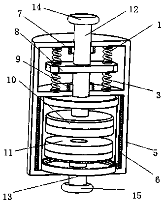
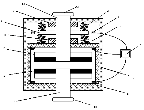
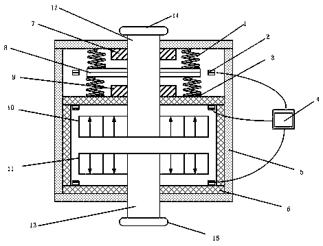
[0014] The invention provides a double-acting cylinder-type electric permanent magnet spring. There are permanent magnets and conductors in the housing. The relative movement of the permanent magnet and the surrounding conductors generates an induced magnetic field and repulsion to realize corresponding functions. Therefore, it has a wide range of applications and has an excellent market. prospect.

[0015] As an embodiment of the present invention, the present invention provides a double-acting cylindrical electro-permanent magnet spring, which includes an upper mechanical spring 1, a lower mechanical spring 3, a controller 4, a housing 5, a conductor 6, an upper electromagnet 7, and an armature. 8. Lower electromagnet 9, upper permanent magnet 10, lower permanent magnet 11, upper motion shaft 12 and lower motion shaft 13. There are mechanical ...


PUM


Abstract

The invention discloses a cylindrical electronic permanent-magnet spring with dual effects. The upper end of an upper movement shaft penetrates out of a shell, the lower end of the upper movement shaft penetrates through a mechanical part, the end of the lower end of the upper movement shaft is located in a permanent-magnet part, the end, penetrating out of the upper end of the shell, of the lower end of lower movement shaft is located in the permanent-magnet part, and an armature is located in the mechanical part and fixed to the upper movement shaft; the outer side of the upper portion ofthe armature is connected with the inner wall of the upper portion of the mechanical part through upper mechanical spring bodies, and the outer side of the lower portion of the armature is connectedwith the inner wall of the lower portion of the mechanical part through lower mechanical spring bodies. An upper electromagnet is arranged at the upper portion of the mechanical part, a lower electromagnet is arranged at the lower portion of the mechanical part, the upper movement shaft penetrates through the middles of the upper electromagnet and the lower electromagnet, the inner wall of the permanent-magnet part is provided with conductors, an upper permanent magnet and a lower permanent magnet are arranged in the permanent-magnet part, the permanent magnet is arranged at the end of the upper end of the lower movement shaft, and the upper permanent magnet is arranged at the end of the lower end of the upper movement shaft. Through the relative movement of the permanent magnets and theconductors at the periphery, an induced magnetic field and repulsive force are generated, the cylindrical electronic permanent-magnet spring achieves corresponding functions, and therefore, the cylindrical electronic permanent-magnet spring has a wide application range and an excellent market prospect.

Description

technical field [0001] The invention relates to the field of accessories, in particular to a double-acting cylindrical electropermanent magnetic spring. Background technique [0002] A spring is a mechanical part that uses elasticity to work. Parts made of elastic materials are deformed under the action of external force, and return to their original shape after the external force is removed. However, the long-term use of traditional springs has a great impact on performance, and the deformation is often difficult to control. For the applicant, a double-acting cylindrical electro-permanent magnetic spring was designed to solve the above problems. Contents of the invention [0003] In order to solve the above-mentioned existing problems, the present invention provides a double-acting cylindrical electro-permanent magnetic spring. There are permanent magnets and conductors in the housing. The relative movement of the permanent magnet and the surrounding conductors generates...

Claims


Application Information

Patent Timeline
Patent Type & Authority Applications(China)
IPC IPC(8): F16F15/03F16F15/04F16F15/067F16F6/00
CPCF16F15/03F16F15/046F16F15/067F16F2222/06F16F2238/026
Inventor 王庆燕曹生让李强司立众
Owner JINLING INST OF TECH
Why Eureka
Try Eureka