
Radio frequency test method for 2M coaxial cable

A technology for coaxial cable and radio frequency testing, which is applied in the field of power communication and can solve the problems such as the inability to transmit digital signals correctly, and the anti-missile connection of the transceiver and termination.

Inactive Publication Date: 2012-08-15
PANJIN POWER SUPPLY COMPANY OF STATE GRID LIAONING ELECTRIC POWER SUPPLY +1
View PDF5 Cites 10 Cited by
  • Summary
  • Abstract
  • Description
  • Claims
  • Application Information

AI Technical Summary

Problems solved by technology

[0003] In order to solve the problem that the digital signal cannot be transmitted correctly due to the fact that the transmitting and receiving end of the line is connected to anti-missile when the professional 2M channel service of the power system is connected, the following technical solution is proposed

Method used


Image

  • Radio frequency test method for 2M coaxial cable
  • Radio frequency test method for 2M coaxial cable
  • Radio frequency test method for 2M coaxial cable

Examples


Embodiment

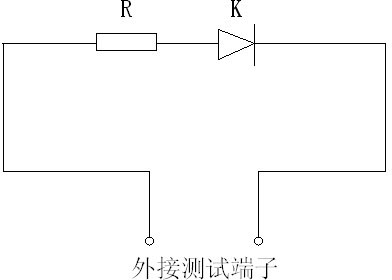
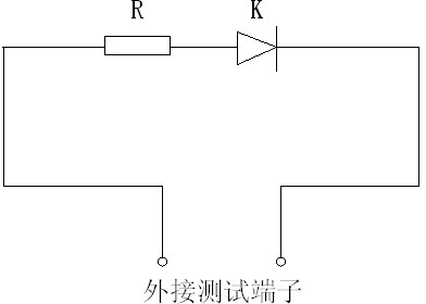
[0012] A 2M coaxial cable radio frequency test method, after connecting the light-emitting diode and the resistor R in series, then connect the anode of the light-emitting diode to the core wire of the 2M coaxial cable through the test terminal, and connect the cathode of the diode to the 2M coaxial cable through the test terminal On the shielding layer of the axial cable, if the diode lights up, it indicates that the connected cable is the sending end of the device, otherwise it is the receiving end.


PUM


Abstract

The invention discloses a radio frequency test method for a 2M coaxial cable. The radio frequency test method for the 2M coaxial cable is characterized in that the anode of a light emitting diode is connected onto a core line of the 2M coaxial cable through a test terminal, and the cathode of the diode is connected onto a shielding layer of the 2M coaxial cable through a test terminal, and if the light emitting diode glows, the connected cable is the emitting end of a set of equipment, otherwise, the connected cable is the receiving end of the equipment. By adopting the radio frequency test method for the 2M coaxial cable in the test process of establishing a communication channel for digital signals, a working staff can accurately judge whether the connected cable is the emitting end or the receiving end of the equipment. The radio frequency test method for the 2M coaxial cable can enable the operating maintenance of the communication system to be simple and quick and greatly improve the work efficiency.

Description

technical field [0001] The invention belongs to the technical field of electric power communication, in particular to the field of power system communication operation and maintenance, and is used for identifying whether a channel is a receiving end or a sending end when a digital signal is connected. Background technique [0002] In the communication industry, the SYV type RF coaxial cable is usually called a 2M cable, and the physical interface mainly includes two types: unbalanced 75 ohms and balanced 120 ohms. In the process of 2M channel debugging, especially when connecting with other professional equipment, it often happens that the receiving end and sending end of the 2M line are connected incorrectly or reversed, which will lead to the failure of digital signal transmission and business failure. damage to the equipment. Contents of the invention [0003] In order to solve the problem that the digital signal cannot be transmitted correctly due to the transmission ...

Claims


Application Information

Patent Timeline
IPC IPC(8): G01R31/02
Inventor 赵宝伟
Owner PANJIN POWER SUPPLY COMPANY OF STATE GRID LIAONING ELECTRIC POWER SUPPLY
Learn More