
Street lamp with adjustable light-emitting angle

An adjustable lighting angle technology, applied in electric light sources, energy-saving lighting, fixed light sources, etc., can solve the problems of limited functional range, single lighting angle, and inability to adjust, and achieve the effect of wide application range and adjustable lighting angle

Inactive Publication Date: 2012-08-22
JIANGSU MODERN LIGHTING GRP CO LTD
View PDF0 Cites 0 Cited by
  • Summary
  • Abstract
  • Description
  • Claims
  • Application Information

AI Technical Summary

Problems solved by technology

[0002] Street lamps are used for lighting and have been used in most cities. The current street lamps have a fixed beam angle. Now when the lamp is installed on the lamp pole, the beam angle is fixed and cannot be adjusted. The beam angle is single and cannot be adjusted according to the specific situation. adjustments, limiting the scope of its functionality

Method used


Image

  • Street lamp with adjustable light-emitting angle
  • Street lamp with adjustable light-emitting angle
  • Street lamp with adjustable light-emitting angle

Examples


Embodiment Construction

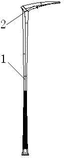
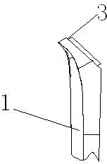
[0012] The present invention installs the lamp 2 on the lamp pole 1, and the joint surface of the two is a symmetrical plane 3 and a corresponding groove structure, such as figure 1 As shown, when the two are installed in the forward direction, the lamp 2 is installed horizontally; figure 2 As shown, when the two are installed in reverse, the lamp 2 is installed vertically, and its luminous angle changes.

[0013] The symmetry plane 3 of the present invention can be an ellipse or other symmetry plane, and the light-emitting cavity is set on the same side as the symmetry plane 3 .


PUM


Abstract

The invention relates to a street lamp, which comprises a lamp post and a lamp, wherein the lamp is arranged on the lamp post, and the mating face of the lamp post and the lamp is a centrosymmetric symmetry plane. According to the street lamp, the lamp post is provided with the centrosymmetric symmetry plane, and the lamp is provided with a corresponding groove. Because of the characteristic that the symmetry plane is symmetric, when the symmetry plane is matched with the groove in the opposite direction, the position of the corresponding lamp on the lamp post is changed, thereby, the light-emitting angle of the lamp is changed. Therefore, compared with a traditional street lamp, the street lamp provided by the invention is adjustable in light-emitting angle, is wider in application range and is more flexible.

Description

technical field [0001] The invention relates to a street lamp, in particular to a street lamp with adjustable luminous angle. Background technique [0002] Street lamps are used for lighting and have been used in most cities. The current street lamps have a fixed beam angle. Now when the lamp is installed on the lamp pole, the beam angle is fixed and cannot be adjusted. The beam angle is single and cannot be adjusted according to the specific situation. adjustments, limiting its functional scope. Contents of the invention [0003] The purpose of the present invention is to provide a street lamp capable of adjusting the lighting angle according to the actual situation. [0004] To this end, the technical solution adopted by the present invention is: the present invention includes a lamp post and a lamp arranged on the lamp post, and the joint surface of the lamp post and the lamp is a symmetric plane about the center. [0005] The symmetrical surface of the light pole is ...

Claims


Application Information

Patent Timeline
Patent Type & Authority Applications(China)
IPC IPC(8): F21S8/08F21V17/06F21W131/103
CPCY02B20/72
Inventor 朱文明
Owner JIANGSU MODERN LIGHTING GRP CO LTD
Learn More