
A passive polarized three-dimensional display device

A three-dimensional display and polarizing technology, applied in optics, optical components, nonlinear optics, etc., can solve problems such as poor moiré pattern and low aperture ratio

Active Publication Date: 2015-10-14
BOE TECH GRP CO LTD +1
View PDF4 Cites 0 Cited by
  • Summary
  • Abstract
  • Description
  • Claims
  • Application Information

AI Technical Summary

Problems solved by technology

[0021] In view of this, the main purpose of the present invention is to provide a passive polarized three-dimensional display device using a patterned retardation film, to increase the vertical viewing angle of the passive polarized three-dimensional display using a patterned retardation film, and compared to other The mode of improving the vertical viewing angle can improve the problem of poor moiré pattern and low aperture ratio in 3D display

Method used


Image

  • A passive polarized three-dimensional display device
  • A passive polarized three-dimensional display device
  • A passive polarized three-dimensional display device

Examples


Embodiment 1

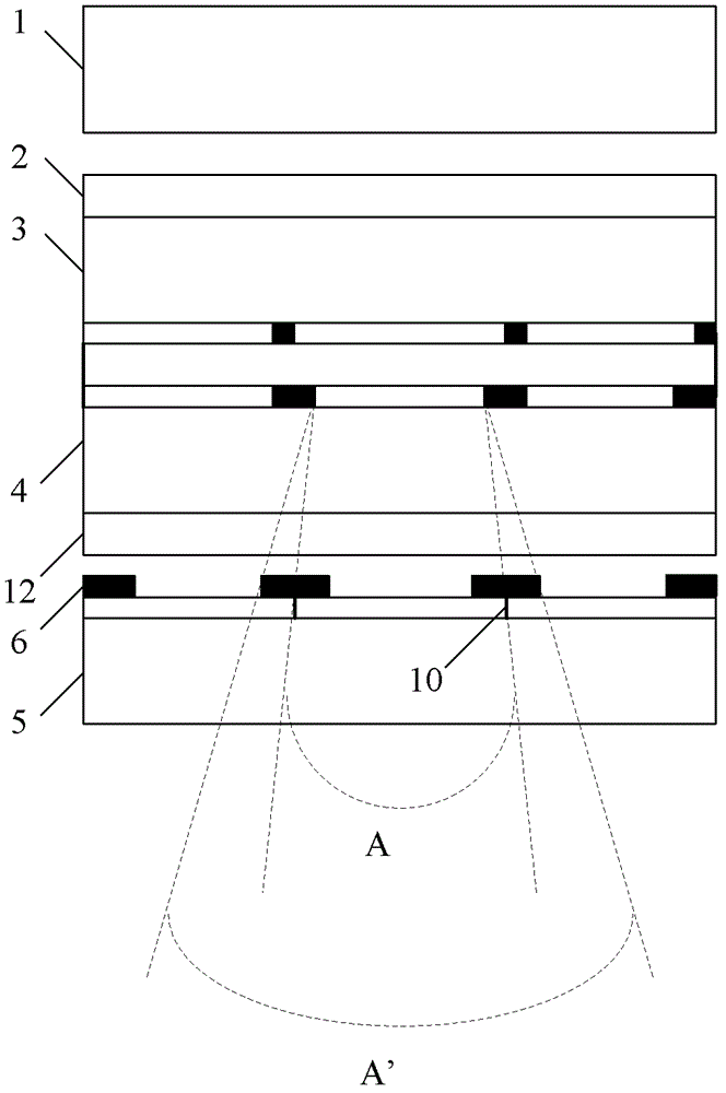
[0044] Such as Figure 6 As shown, the passive polarized 3D display device using a patterned retardation film according to Embodiment 1 of the present invention includes: a backlight unit 1, a first polarizer 2, a TFT array substrate 3, a color filter substrate 4, and a second polarizer arranged in sequence. sheet 12 and pattern retardation film 5. A passive polarizing 3D display device using a patterned retardation film according to Embodiment 1 of the present invention and figure 1 The difference of the passive polarizing 3D display device using the pattern retardation film in the prior art shown is that not only matrix strips are arranged on the film surface of the color filter substrate 4, but also light-shielding strips are arranged on the back of the color filter substrate 4 8, and the light-shielding strips 8 on the back of the color filter substrate 4 have the same width and equal spacing as the matrix strips on the film surface of the color filter substrate 4, so as ...

Embodiment 2

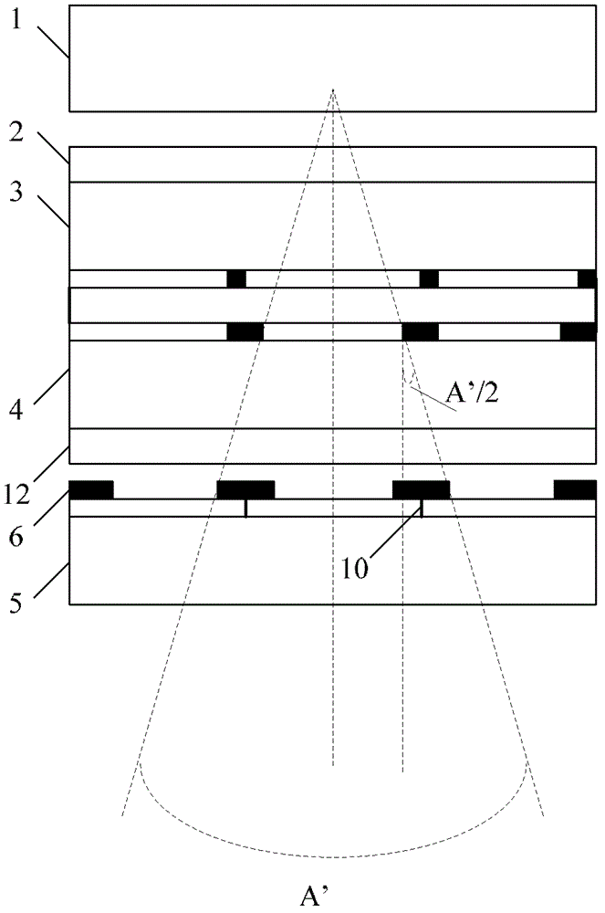
[0054] Such as Figure 7 As shown, the passive polarized 3D display device using the pattern retardation film according to Embodiment 2 of the present invention includes: a backlight unit 1, a first polarizer 2, a TFT array substrate 3, a color filter substrate 4, and a second polarizer arranged in sequence. sheet 12 and pattern retardation film 5. The passive polarized 3D display and figure 1 The difference of the passive polarizing 3D display device using the pattern retardation film in the prior art shown is that: a light-shielding strip 8 is provided on the back of the color filter substrate 4, and the corresponding position of the film surface of the color filter substrate 4 may not be provided with a matrix. strip. Wherein, the dividing line between two adjacent pattern phase difference films is opposite to the middle position of the light-shielding strip 8 on the back side of the color filter substrate 4 corresponding to the dividing line; the preferred mode of relati...


PUM


Abstract

A passive polarized three-dimensional display device comprises a backlight unit (1); a first polaroid (2); an array substrate (3) which is formed with a plurality of gate lines and data lines at one side away from the first polaroid, the gate lines and the data lines intersect with each other so that pixel units arranged in a matrix are defined, each pixel unit comprising a thin film transistor and a pixel electrode; a colour film substrate (4) which is arranged opposite to the array substrate and is formed with a colour filter at one side opposite to the array substrate; a second polaroid (12); and a patterned retarder film (5) which has a plurality of patterned retarders (11) formed thereon, one side of the colour film substrate away from the array substrate is provided with a plurality of shutter bars (8), and the middle position of each shutter bar corresponds to the position of a demarcation line (10) between two adjacent patterned retarders on the corresponding patterned retarder film.

Description

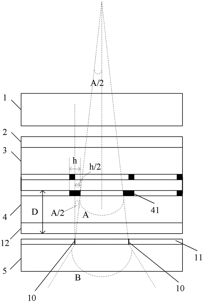
technical field [0001] The invention relates to the field of three-dimensional (3D) display, in particular to a passive polarized 3D display device using a pattern retardation film. Background technique [0002] Such as figure 1 As shown, the passive polarized 3D display device using the pattern retardation film in the prior art includes: a backlight unit 1, a first polarizer 2, an array substrate 3, a color filter substrate (CF) 4, a second polarizer arranged in sequence sheet 12 and a patterned retarder film (Patterned Retarder Film) 5; wherein, the side of the color filter substrate 4 facing the array substrate 3 (this side is called the film surface) is provided with a black matrix, and the black matrix has a plurality of matrix bars 41 . The vertical viewing angle B=arc sin(refractive index×sin(A)) of the passive polarized 3D display using the pattern retardation film, the angle A=2arc tan(h / 2D); wherein, the refractive index can be taken as an empirical value of 1.5,...

Claims


Application Information

Patent Timeline
Patent Type & Authority Patents(China)
IPC IPC(8): G02B27/26H04N13/04G02B30/25
CPCG02B27/26G02F1/133512G02F1/13363G02F2001/133562G02F2001/133631G02F2413/01H04N13/0434G02B30/25G02F1/133562G02F1/133631H04N13/337
Inventor 申莹
Owner BOE TECH GRP CO LTD
Learn More