Liquid discharging apparatus and control method thereof

A control method and liquid technology, applied in printing devices, printing, etc., can solve problems such as leakage

Active Publication Date: 2012-09-05
SEIKO EPSON CORP
View PDF7 Cites 9 Cited by
  • Summary
  • Abstract
  • Description
  • Claims
  • Application Information

AI Technical Summary

Problems solved by technology

Therefore, when filling the ink into the printing head, when the circulation pump is rotationally driven while the nozzle surface is covered by the suction cap, the ink may leak from the nozzle depending on the flow velocity of the ink.

Method used


Image

  • Liquid discharging apparatus and control method thereof
  • Liquid discharging apparatus and control method thereof
  • Liquid discharging apparatus and control method thereof

Examples


Embodiment Construction

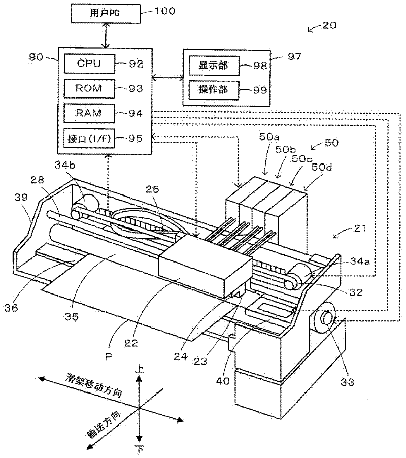
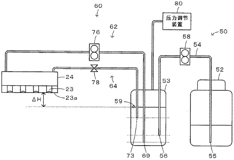
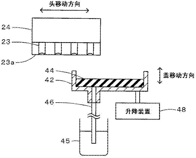
[0024] Embodiments of the present invention will be described below using the drawings. figure 1 is a configuration diagram showing an outline configuration of an inkjet printer 20 as an embodiment of the present invention, figure 2 is a structural diagram showing an outline of the structure of the ink circulation system 50, image 3 It is a configuration diagram showing the outline of the configuration of the capping device 40 .

[0025] Such as figure 1 As shown, the inkjet printer 20 of this embodiment includes: a printer mechanism 21 that ejects ink droplets from the plurality of nozzles 23 formed on the print head 24 to the paper P conveyed on the platen 36 to implement Printing process; capping device 40, which is arranged near the right end of platen 36, and can independently seal the plurality of nozzles 23 of printing head 24; controller 90, which controls the entire device; operation panel 97, which has a display unit 98 for notifying the user of various informat...


PUM


Abstract

When filling a printing head (24) with ink, ink in a sub-tank (53) is circulated through a forward path port (69), a forward path (62), the printing head, a return path (64), a return path port (73), and the sub-tank by pumping ink from the forward path port side to the printing head side by a circulation pump (76) in a state where a plurality of nozzles is sealed by bringing a contact member (44) of a capping device (40) into contact with a nozzle formation surface. Thereafter, sealing of the plurality of nozzles by the capping device is released while pressurizing the sub-tank by a pressure adjusting device (80).

Description

technical field [0001] The invention relates to a liquid ejecting device and a control method thereof. Background technique [0002] Conventionally, as such a liquid ejecting device, a device has been proposed, that is, the device is provided with: a printing head for ejecting ink; an ink tank for storing ink; and a first ink flow path for Ink is supplied from the ink tank to the manifold of the printing head; the second ink flow channel for recovering the ink from the manifold to the ink tank; the pump for ink circulation, which is provided on the first ink flow channel; the on-off valve, It is provided on the second ink flow path; a suction cap for covering the nozzle surface of the printing head; and a suction pump connected to the suction cap through a suction tube (for example, refer to Patent Document 1). In this device, when filling ink into the printing head, first, the nozzle surface of the printing head is covered with a suction cap, and the on-off valve is opened...

Claims


Application Information

Patent Timeline
Patent Type & Authority Applications(China)
IPC IPC(8): B41J2/01B41J29/393
CPCB41J2/175B41J2/16505
Inventor 小池薰熊谷利雄
Owner SEIKO EPSON CORP
Why Eureka
Try Eureka