LED backlight drive circuit, backlight module and liquid crystal display device

A technology of backlight drive circuit and resistor, which is applied in the direction of electric lamp circuit layout, lighting device, light source, etc., can solve the problems of output short circuit, circuit power consumption, loss, etc., and achieve the effect of solving the flickering effect of starting up

Active Publication Date: 2012-09-12
SHENZHEN CHINA STAR OPTOELECTRONICS TECH CO LTD
View PDF6 Cites 24 Cited by
  • Summary
  • Abstract
  • Description
  • Claims
  • Application Information

AI Technical Summary

Problems solved by technology

Adding a discharge resistor directly is equivalent to adding an extra load, which will consume the power of the circuit all the time, ...

Method used


Image

  • LED backlight drive circuit, backlight module and liquid crystal display device
  • LED backlight drive circuit, backlight module and liquid crystal display device
  • LED backlight drive circuit, backlight module and liquid crystal display device

Examples


Embodiment Construction

[0027] The present invention will be further described below in conjunction with the accompanying drawings and preferred embodiments.

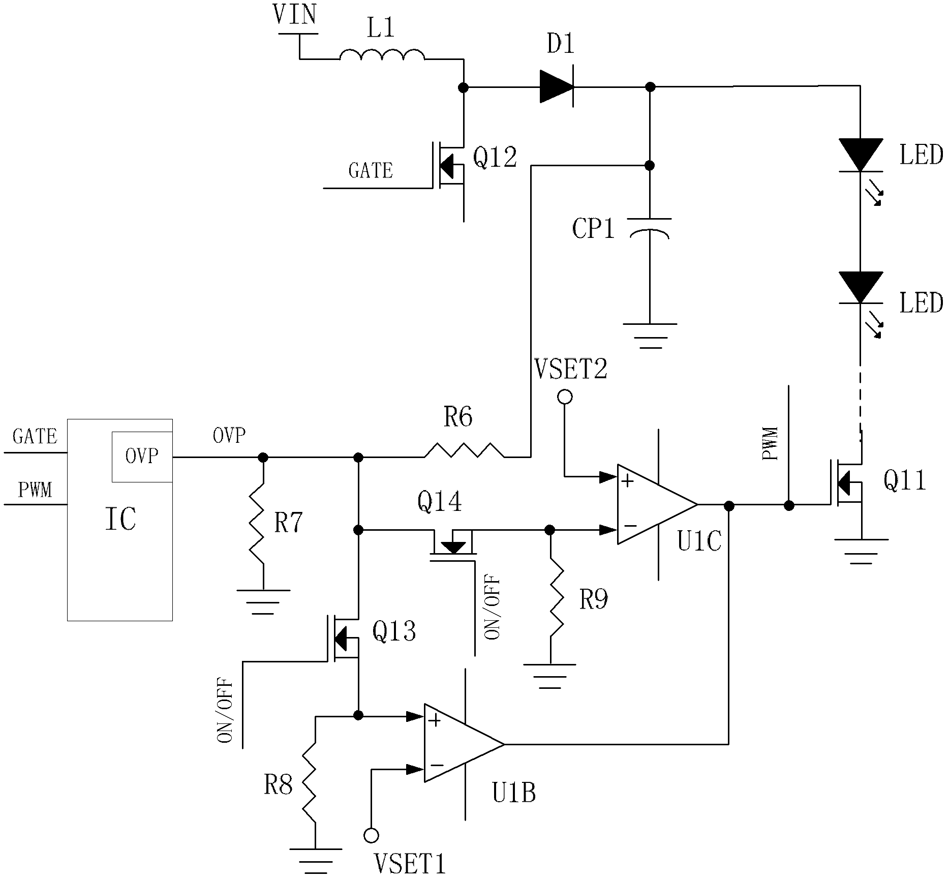
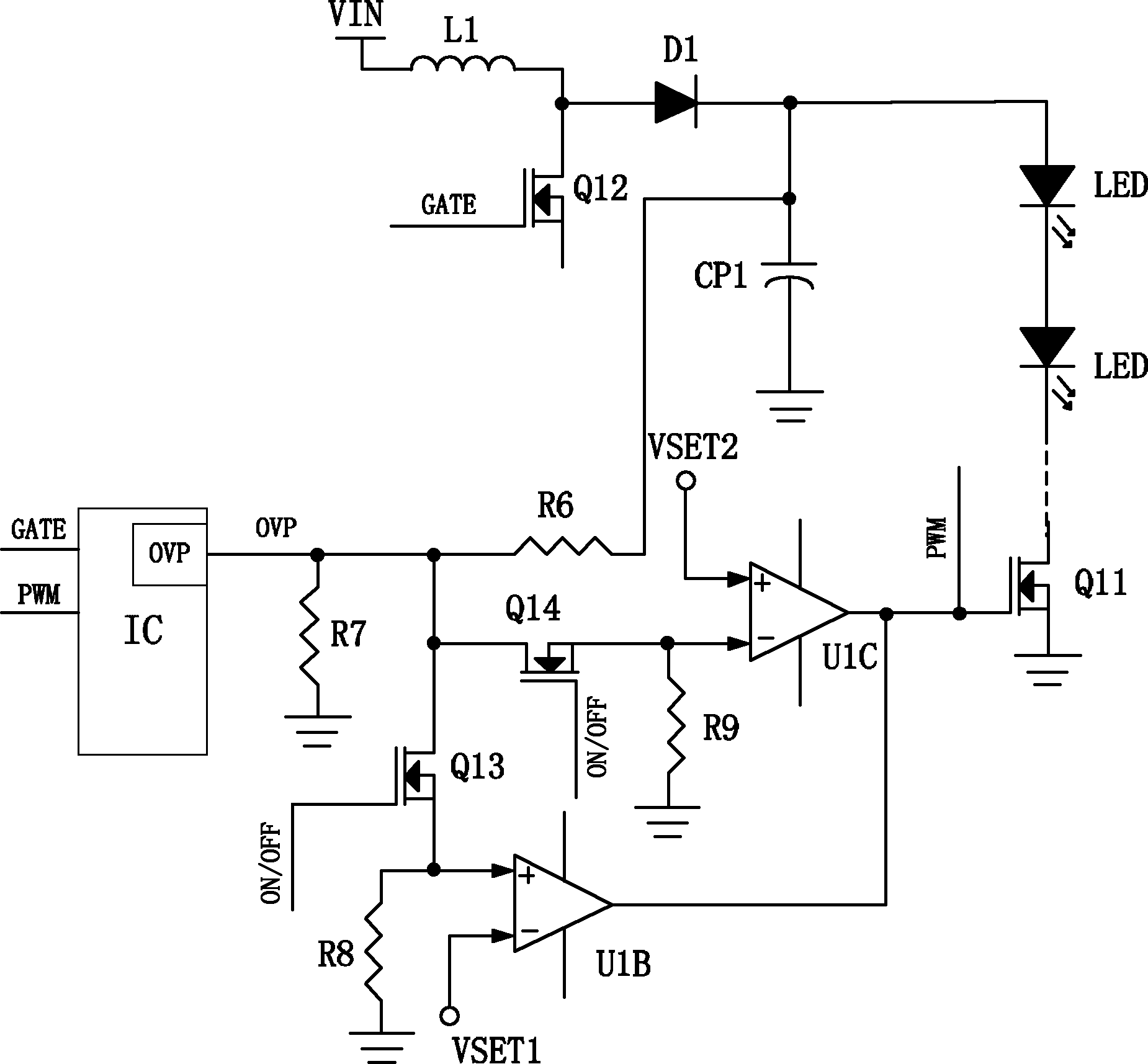
[0028] like figure 2 As shown, a liquid crystal display device includes a liquid crystal panel, and a backlight module that provides a light source for the liquid crystal panel. The backlight module includes an LED backlight drive circuit, and the backlight drive circuit includes a power supply, an output terminal of the power supply, and a ground terminal. An output capacitor CP1 and an LED light bar with a first controllable switch Q11 connected in series are arranged in parallel. The LED backlight drive circuit also includes a first comparator U1B, the negative pole of the first comparator U1B is connected to the first reference voltage VSET1, and the positive pole is coupled to the output terminal of the power supply, and is used to collect the output voltage of the power supply as a comparison voltage, and the output terminal of the firs...


PUM


Abstract

The invention discloses an LED backlight drive circuit, a backlight module and a liquid crystal display device. The LED backlight drive circuit comprises a power source and a first comparator, an output capacitor is parallelly connected and an LED lamp bar of a first controllable switch is serially connected between an output end and a grounding end of the power source, a cathode of the first comparator is connected with first reference voltage, an anode of the first comparator is coupled with the output end of the power source, and an output end of the first comparator is coupled with a control end of the first controllable switch. When anode voltage of the first comparator exceeds cathode voltage of the same, the output end of the first comparator drives the first controllable switch to be switched on. The LED lamp bar is controlled to be connected at the predetermined voltage, and accordingly, even if the output capacitor stores electric quantity, an LED cannot be driven to be turned on, and the first controllable switch can be switched on only on the condition that complete start-up is achieved and output voltage reaches a preset voltage value, and further the problem of flickering in start-up is solved.

Description

technical field [0001] The invention relates to the field of liquid crystal display, and more specifically relates to an LED backlight driving circuit, a backlight module and a liquid crystal display device. Background technique [0002] Existing liquid crystal display devices mostly use LEDs as backlight sources. figure 1 It is an existing LED driver (DRIVER) circuit. When the ON / OFF signal is switched at a very short time interval, the charge of the output capacitor C1 is not released in time when it is turned off immediately after starting up, and the charge will be released when it is turned on next time. It will be poured into the LED first, and then it will be the normal LED drive, because the LED drive circuit will have a certain delay time every time it is turned on, so the LED will light up twice, causing flickering. In addition, when the voltage rises slowly, the LED will conduct a small current before reaching the normal voltage. At this time, the LED rises slowl...

Claims


Application Information

Patent Timeline
IPC IPC(8): H05B37/02G09G3/36
CPCY02B20/30H05B45/3725
Inventor 杨翔高新明黎飞
Owner SHENZHEN CHINA STAR OPTOELECTRONICS TECH CO LTD
Why Eureka
Try Eureka