Method and apparatus to create uniform mixing in connection with a hydrometalurgical process

A technology of hydrometallurgy and process, applied in the field of producing uniform mixing and devices related to hydrometallurgy process, which can solve the problems of fine grinding of crystals, mechanical wear, etc.

Inactive Publication Date: 2012-09-12
OUTOTEC OYJ
View PDF6 Cites 5 Cited by
  • Summary
  • Abstract
  • Description
  • Claims
  • Application Information

AI Technical Summary

Problems solved by technology

High mixing intensities can also cause mechanical wear on precipitates or c...

Method used


Image

  • Method and apparatus to create uniform mixing in connection with a hydrometalurgical process
  • Method and apparatus to create uniform mixing in connection with a hydrometalurgical process
  • Method and apparatus to create uniform mixing in connection with a hydrometalurgical process

Examples


Embodiment Construction

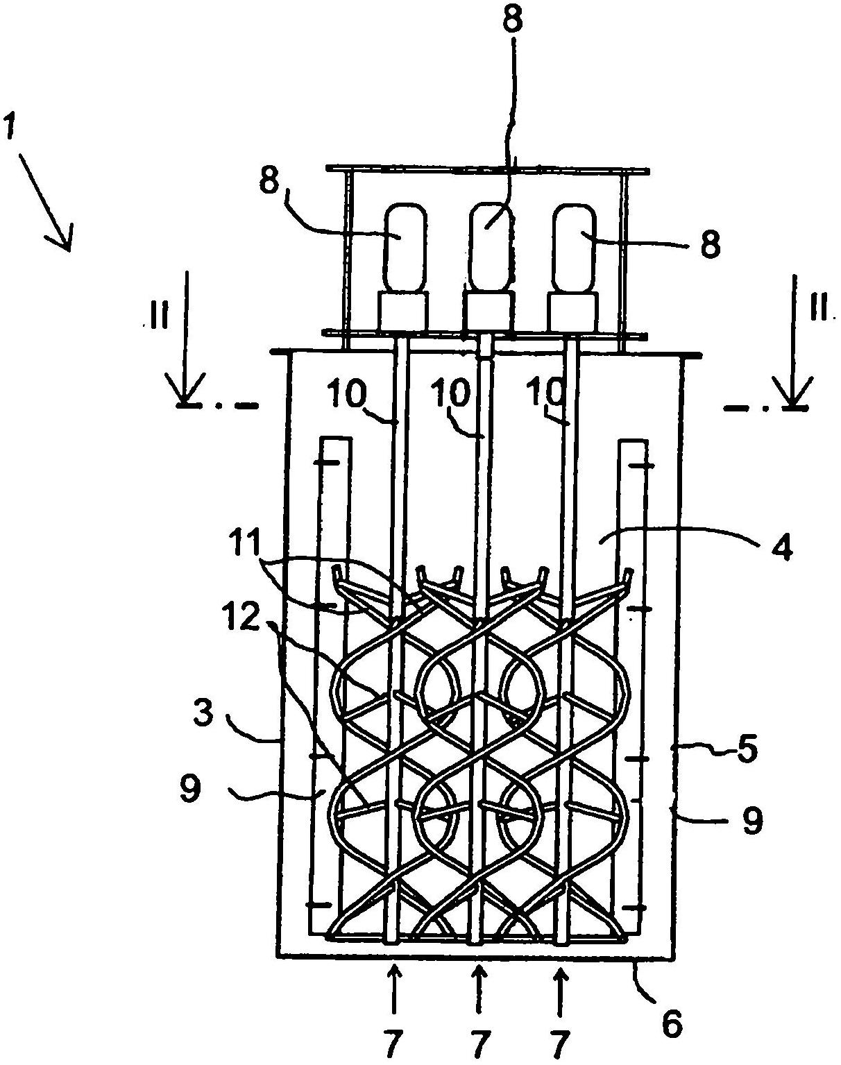
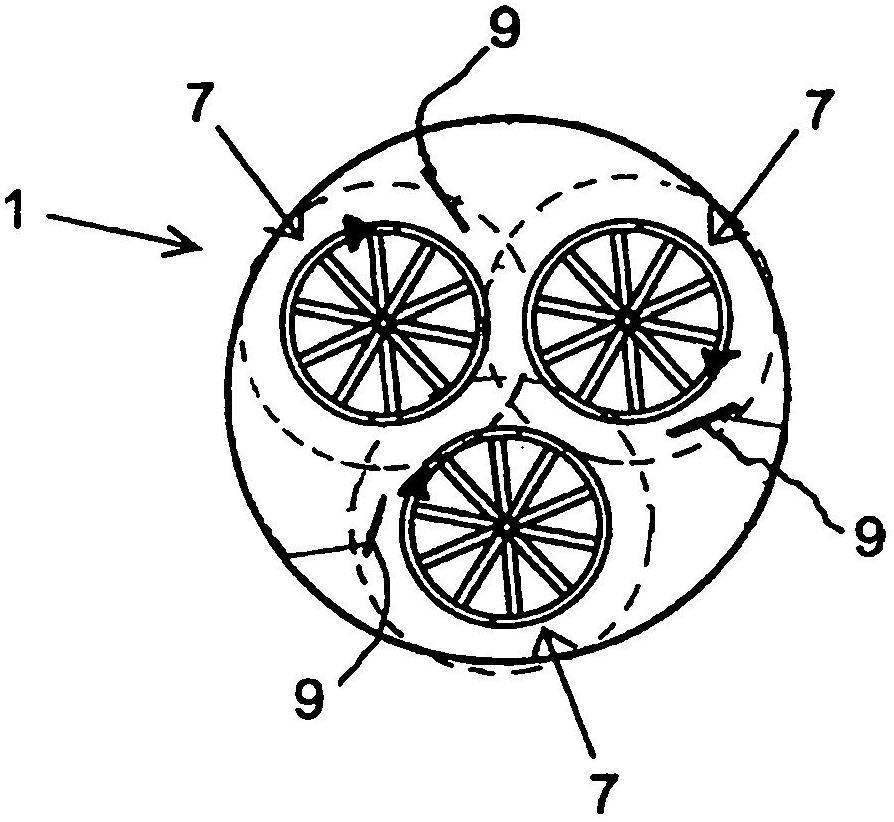
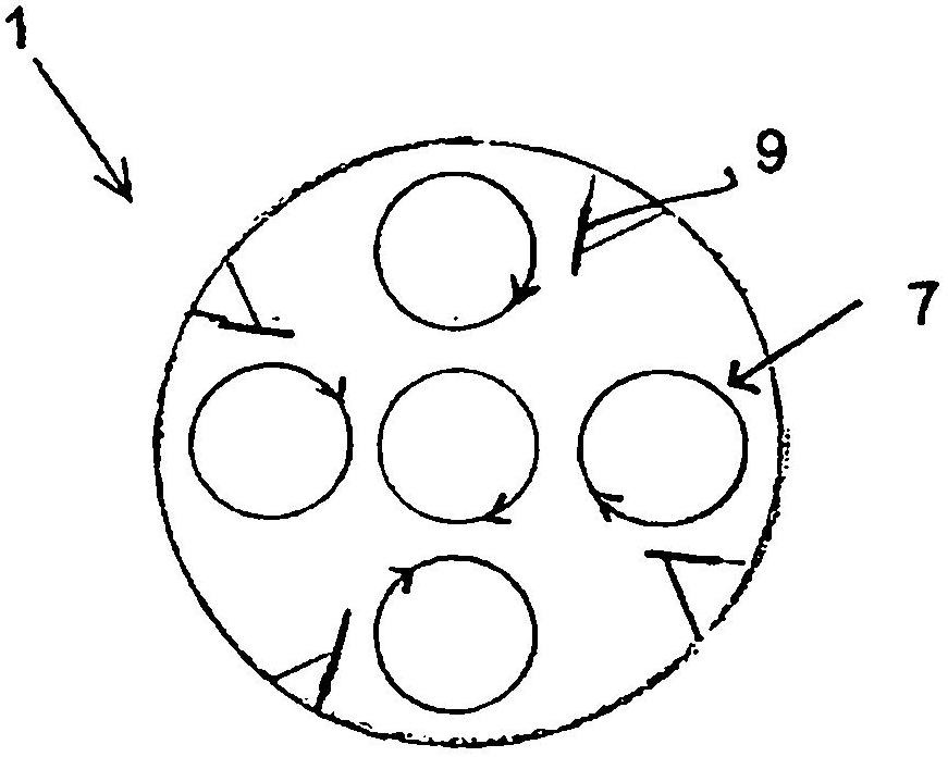
[0028] Homogeneous mixing at low mixing intensities, but still extending across the reactor volume, according to the invention is achieved by means of a helical rotor mixer comprising at least three separate helical rotors. The mixer is placed in a reactor, which is roughly in the shape of an upright cylinder. A solution to be crystallized, a liquid containing solids, or two mutually soluble liquids are mixed in a reactor to bring about crystallization, precipitation or a suspension in solvent extraction. The main mixing zone of the helical rotor mixer comprises more than 70%, preferably more than 80%, of the effective volume of the reactor. Effective volume means the volume in the reactor between the bottom of the reactor and the surface of the liquid. In the case of a helical rotor, the primary mixing zone comprises the area remaining within the helical rotor plus an area outside the helical rotor of approximately the size of the cross-sectional area of ​​the helical rotor....


PUM


Abstract

The invention relates to a method and apparatus for mixing one or several solutions in a reactor (3) in conjunction with a hydrometallurgical process, such as precipitation, crystallisation or forming a suspension in solvent extraction. Mixing with a vertical circulation flow is created in the reactor by means of a multi-part mixer (1), so that the primary mixing zone in which the mixer rotates is over 70 % of the effective volume of the reactor, whereby the homogenous, low-intensity mixing needed for precipitation, crystallisation and/or the mixing stage of solvent extraction is achieved.

Description

technical field [0001] The present invention relates to a method and apparatus which allow mixing of one or more solutions in a reactor in a hydrometallurgical process to bring about the desired suspension in precipitation, crystallization or solvent extraction. The apparatus comprises a reactor and placed therein a multipart helical rotor mixer having in its helical rotor a helical strip which rotates about and is supported to the shaft. Background technique [0002] Inhomogeneous mixing is a problem for many hydrometallurgical unit processes. In conventional schemes, blade or turbine type mixers usually rotate in a volume in which the main mixing zone is at most about 3% of the total volume of the reactor used. This means that the shaft forces generated by the mixer are directed very strongly in the immediate vicinity of the mixer. As a result, the specific volumetric mixing intensity reaches tens of kilowatts per cubic meter around the axis, but drops significantly towa...

Claims


Application Information

Patent Timeline
IPC IPC(8): B01F7/24C22B3/26B01F23/53B01F27/1145B01F27/86B01F27/922C02F11/147
CPCB01D21/01B01D21/08B01D21/286C02F1/34C02F1/52C02F2301/024C10G1/00C02F11/147B01F23/53B01F27/11451B01F27/1145B01F27/86B01F27/922B01F27/92
Inventor T·里塔萨洛J·瓦尔诺L·利亚J·吕拉P·佩卡拉B·内曼
Owner OUTOTEC OYJ
Why Eureka
Try Eureka