X-ray CT system

An X-ray and X-ray tube technology, applied in the field of X-ray CT devices, can solve the problems of reduced tube voltage waveform repeatability, high X-ray images, and shaking

Active Publication Date: 2012-09-19
TOSHIBA MEDICAL SYST CORP
View PDF7 Cites 4 Cited by
  • Summary
  • Abstract
  • Description
  • Claims
  • Application Information

AI Technical Summary

Problems solved by technology

[0021] As explained above, there is a problem that the repeatability of the tube voltage waveform decreases when the switching frequency of the tube voltage is high in cardiac diagnosis, etc., and close to the operating frequency of the inverter.
[0022] In addition, although the rotating ring equipped with X-ray tubes, X-ray detectors and X-ray generators, etc. is equipped with a balance device, it still shakes during rotation.
Therefore, there is a problem that high-quality X-ray images cannot be obtained due to such shaking

Method used


Image

  • X-ray CT system
  • X-ray CT system
  • X-ray CT system

Examples


no. 1 Embodiment approach

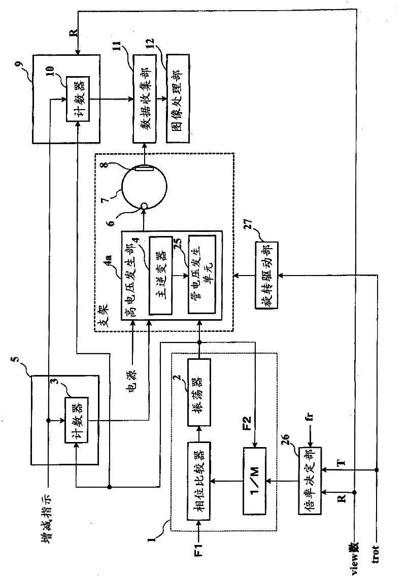
[0043] Refer to the first embodiment of the X-ray CT apparatus figure 1 Be explained. figure 1 is a block diagram showing the configuration of the X-ray CT apparatus.

[0044] The X-ray CT apparatus has: a multiplier 1 for synchronizing the inverter operating frequency fi with the tube voltage switching frequency fs; a high voltage generating part 4a having a main inverter 4 and a tube voltage generating unit 25; having a counter 3, The increase and decrease timing generation part 5 that outputs the indication of switching tube voltage to the main inverter 4; the rotating ring 7 that the X-ray tube 6 and the X-ray detector 8 are arranged opposite; The data collection part 11 that the X-ray that detects is collected; Have counter 10, the collection timing generation part 9 that outputs collection timing indication to data collection part 11; Rebuild the image of X-ray image according to the X-ray that is collected by data collection part 11 The processing part 12; the rotat...

no. 2 Embodiment approach

[0065] In the first embodiment, an X-ray CT apparatus that obtains high-quality X-ray images by synchronizing the inverter operating frequency fi with the tube voltage switching frequency fs has been described.

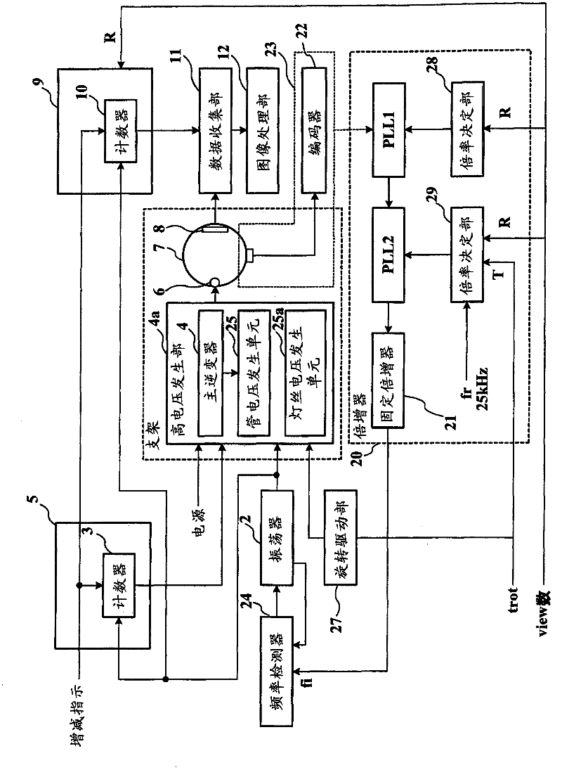
[0066] Furthermore, in order to obtain high-quality X-ray images, refer to figure 2 The X-ray CT apparatus according to the second embodiment having the multiplier 20 for synchronizing the inverter operating frequency fi with the vibration generated during the rotation of the X-ray tube 6 has been described. In addition, the same reference numerals are used for the same configuration of the X-ray apparatus as that of the first embodiment, and description thereof will be omitted.

[0067] figure 2 is a block diagram showing the configuration of the X-ray CT apparatus. like figure 2 As shown, the multiplier 20 has variable multipliers PLL1 , PLL2 and a fixed multiplier 21 . In addition, an encoder 22 and a frequency detector 24 are also provided. Here, since the...

no. 3 Embodiment approach

[0088] Next, referring to the X-ray CT apparatus according to the third embodiment Figure 7-15 Be explained.

[0089] Figure 7 It is the circuit diagram of the X-ray generator. like Figure 7 As shown, the anode (anode) 61 of the X-ray tube 6 is connected to the positive terminal of the high voltage power supply 64 , and the cathode (cathode) 62 is connected to the negative terminal of the high voltage power supply 64 . A filament power supply 65 is provided for causing the cathode 62 to generate thermoelectrons.

[0090] Figure 8 is the oblique view of the cup, Figure 9 Yes Figure 8 A cross-sectional view of line A-A, Figure 10 Yes Figure 8 Cross-sectional view of line B-B. like Figure 8-10 As shown, cathode 62 is disposed in a groove in cup 63 . One contact of the cathode 62 is connected to the cup 63 and the other contact is at potential relative to the cup 63 . In addition, the cathode 62 is also sometimes referred to as a filament.

[0091] When the c...


PUM


Abstract

Embodiments of the invention relate to an X-ray CT system. An X-ray tube and an X-ray detector are arranged opposing one another. X-rays are irradiated from the X-ray tube by revolving around the subject. An X-ray image is obtained based on the X-rays that penetrate the subject and are detected by the X-ray detector. The high voltage generator has an inverter that supplies a voltage to the X-ray tube by switching to a predetermined operating frequency during revolution of the X-ray tube. Regarding the frequency adjustable part, the operating frequency of the inverter is adjustable such that it is a multiple of the collection rate, which is the number of X-ray images obtained per one revolution of the X-ray tube. The timing generator may adjust the voltage supplied to the X-ray tube at a timing synchronized with the operating frequency of the inverter.

Description

[0001] related application [0002] This application is based on Japanese patent application 2011-052332 (filing date: 3 / 10 / 2011) and enjoys the priority benefit of this application. This application incorporates the entire content of this application by reference. technical field [0003] Embodiments of the present invention relate to X-ray CT apparatuses. Background technique [0004] Conventionally, as means for material analysis, for example, dual energy (Dual energy) CT is used in which two different tube voltages are applied to an X-ray tube and imaging is performed using X-rays irradiated from the X-ray tube. When imaging a substance with X-rays in which the tube voltage is changed, the substance shows a change in CT value inherent to the substance. Based on this change in CT value, it is possible to analyze, for example, a contrast agent of a blood vessel, calcified tissue, and the like. [0005] As an example of dual-energy CT, there is a case where two X-ray tub...

Claims


Application Information

Patent Timeline
Patent Type & Authority Applications(China)
IPC IPC(8): H05G1/08A61B6/03
CPCA61B6/482A61B6/4435A61B6/035A61B6/405A61B6/503H05G1/58
Inventor 石山文雄
Owner TOSHIBA MEDICAL SYST CORP
Why Eureka
Try Eureka