Winding wiring structure for ultra-large capacity on-load variac

A voltage regulating transformer and voltage regulating winding technology, applied in the direction of transformer/inductor coil/winding/connection, etc., can solve the problem of high oscillation potential of voltage regulating winding

Active Publication Date: 2005-04-27
TBEA SHENYANG TRANSFORMER GRP CO LTD
View PDF0 Cites 3 Cited by
  • Summary
  • Abstract
  • Description
  • Claims
  • Application Information

AI Technical Summary

Problems solved by technology

However, if the self-coupling operation voltage of the two windings is very close, if the super-large-capacity auto-coupling on-load tap-changing transformer with power greater than 750MVA still adopts this structure, the n

Method used


Image

  • Winding wiring structure for ultra-large capacity on-load variac
  • Winding wiring structure for ultra-large capacity on-load variac
  • Winding wiring structure for ultra-large capacity on-load variac

Examples


Embodiment Construction

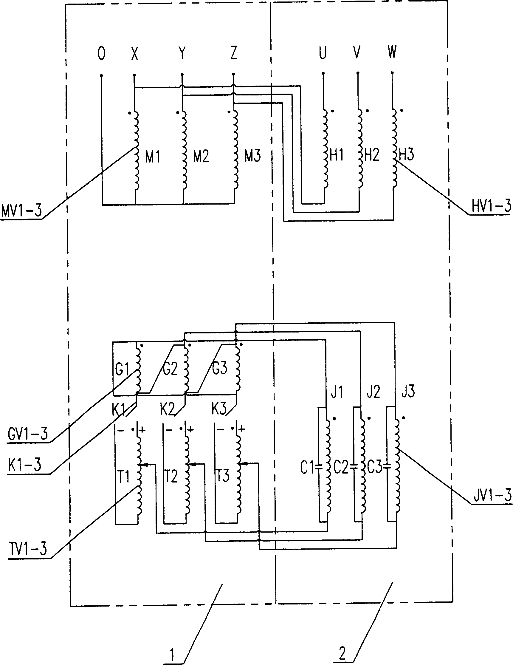
[0011] According to the winding structure of the ultra-large capacity self-coupling on-load transformer of the present invention, a 900MVA auto-coupling on-load voltage regulating transformer is designed, and its winding circuit structure is as attached figure 1 shown. M of common winding MV1-3 1 , M 2 , M 3 Three coils, G of GV1-3 of excitation winding I 1 , G 2 , G 3 T of the three coils and the voltage regulating winding TV1-3 1 , T 2 , T 3 The three coils are sequentially set on the three iron core columns of the constant flux device body, forming the constant flux device body—the public transformer (M transformer). While the H of the series winding HV1-3 1 、H 2 、H 3 Three coils with field winding II JV1-3 J 1 、J 2 、J 3 The three coils are successively set on the three iron core columns of the flux transformer body, forming the flux transformer body—series transformer (S transformer). The two bodies are installed together in the transformer oil tank.

[001...


PUM


Abstract

The super-large capacity auto voltage-regulating transformer has constant magnetic flux body with common winding, exciting winding I and voltage regulating winding on its iron core column, and variant magnetic flux body with exciting winding II and serial winding on its iron core column. It has the serial connection of common winding and serial winding, and the serial connection of exciting winding I, exciting winding II and voltage regulating winding. The voltage regulating winding may have 9 or 17 taps connected via two way switch with exciting winding I and exciting winding II; and the turn number ratio between the exciting winding II and the serial winding is 0.8-2.0. The present invention regulates the winding work turn number and magnetic field direction via changing the live switch, and has raised capacity of resisting high vibration potential caused by lightning shock wave.

Description

technical field [0001] According to the International Patent Classification Table, the invention belongs to the technical field of autotransformer winding wiring structure, and in particular relates to a winding wiring structure of an ultra-large-capacity autotransformer on-load tap changer. Background technique [0002] A part of the auto-on-load voltage regulating transformer in the prior art is a series winding on-load voltage regulation, and the voltage regulating winding is usually connected in series to the end of the series winding, and then connected in series with the common winding. The potential per turn of each winding is constant, and the voltage regulation is realized by changing the number of turns of the voltage regulation winding. The output voltage difference between the series voltage regulating winding and the common winding of the self-coupling OLTC transformer is large, and the number of turns of the series winding is generally close to the number of tu...

Claims


Application Information

Patent Timeline
IPC IPC(8): H01F27/28
Inventor 高兴耀孙勇钟俊涛
Owner TBEA SHENYANG TRANSFORMER GRP CO LTD
Why Eureka
Try Eureka