Multi-anode electric field synthesis device

A synthesis device, multi-anode technology, applied in the field of electrochemistry

Pending Publication Date: 2020-10-13
山西师范大学
View PDF4 Cites 2 Cited by
  • Summary
  • Abstract
  • Description
  • Claims
  • Application Information

AI Technical Summary

Problems solved by technology

[0002]Electrolysis devices are widely used, such as in electrowinning or metal purification, etc., but traditional electrolysis devices are composed of an anode and a cathode, which means , if the cathode is a carbon rod, and the anode is a metal, when a voltage is applied, the carbon rod cathode is stripped into graphene and dispersed into the solution, while the anode can only have one metal dissolved into the solutio

Method used


Image

  • Multi-anode electric field synthesis device
  • Multi-anode electric field synthesis device
  • Multi-anode electric field synthesis device

Examples


Embodiment 1

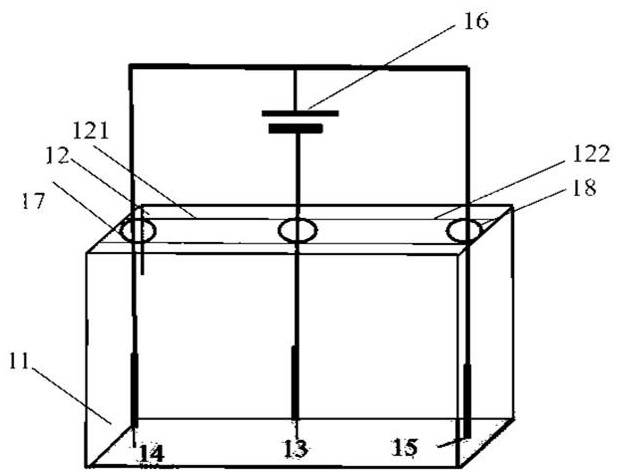
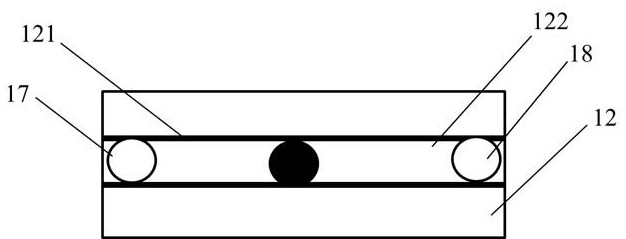
[0029] Such as figure 1 A multi-anode electric field synthesis device is shown, including a square electrolytic cell 11, an electrolytic cell cover 12, a cathode (carbon rod) 13, a first anode Cu14, a second anode Pt15, an electrolyte solution (PC + 0.1M TBABF4) and a DC Power supply 16, the electrolytic cell cover 12 is located at the top of the electrolytic cell 11, and is detachably installed on the electrolytic cell 11, and the first anode Cu14 and the second anode Pt15 are connected to the positive pole of the power supply 16 in parallel by wires; the electrolytic cell cover 12 A first track 121 and a second track 122 are arranged on it, and the first anode Cu14 and the second anode Pt15 can slide along the first track 121 and the second track 122 through the first knob 17 and the second knob 18 respectively. By moving the first knob 17 and the second knob 18, the distance from the first anode Cu14 and the second anode Pt15 to the cathode 13 is changed, so that the first ...

Embodiment 2

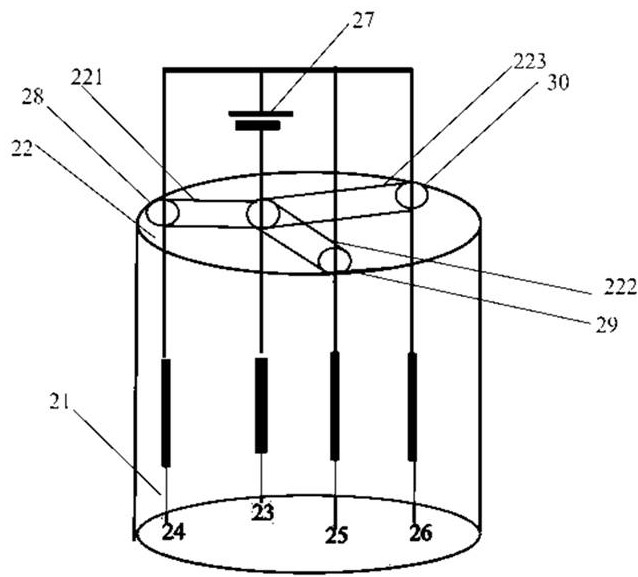
[0031] Such as figure 2 A multi-anode electric field synthesis device shown includes a circular electrolytic cell 21, an electrolytic cell cover 22, a cathode (carbon rod) 23, a first anode Co24, a second anode Cu25, a third anode Pt26, an electrolyte solution (PC + 0.1M TBABF4) and a DC power supply 27, the electrolytic cell cover 22 is located on the top of the circular electrolytic cell 21, and is detachably installed on the circular electrolytic cell 21, the first anode Co24, the second anode Cu25 and the third anode Pt26 Connect to the positive pole of the power supply 27 in parallel by wires; the first track 221, the second track 222 and the third track 223 are arranged on the electrolytic cell cover 22, and the first anode Co24, the second anode Cu25 and the third anode Pt26 are respectively The first knob 28 , the second knob 29 and the third knob 30 can slide along the first track 221 , the second track 222 and the third track 223 . By moving the first knob 28, the ...

Embodiment 3

[0033] Such as image 3The multi-anode electric field synthesis device shown includes a circular electrolytic cell 31, an electrolytic cell cover 32, a cathode (carbon rod) 33, a first anode Fe34, a second anode Co35, a third anode Cu36, a fourth anode Pt37, Electrolyte solution (PC + 0.1MTBABF4) and DC power supply 38. The electrolytic cell cover 32 is located on the top of the circular electrolytic cell 31 and is detachably installed on the circular electrolytic cell 31. The first anode Fe34, second anode Co35, The third anode Cu36 and the fourth anode Pt37 are connected in parallel to the positive pole of the power supply 38 by wires; the electrolytic cell cover 32 is provided with a first track 321, a second track 322, a third track 323 and a fourth track 324. An anode Fe34, a second anode Co35, a third anode Cu36 and a fourth anode Pt37 can pass through the first knob 39, the second knob 310, the third knob 311 and the fourth knob 312 respectively along the first track 32...


PUM


Abstract

The invention provides a multi-anode electric field synthesis device which comprises an electrolytic tank, an electrolytic tank cover, a plurality of anodes and a plurality of cathodes. The anodes andthe cathodes are arranged in the electrolytic tank, an electrolytic power supply is connected between the anodes and the cathodes, the electrolytic tank cover is located at the top of the electrolytic tank and detachably mounted on the electrolytic tank, and the plurality of anodes are connected in parallel to a positive electrode of a power supply through wires; and a plurality of tracks are arranged on the electrolytic tank cover, and the plurality of anodes are movably arranged on the tracks. A plurality of metal anodes are adopted, different metals can be dissolved in a same solution through parallel electric fields, and dissolved metal ions are reduced into nanoparticles through an electrolyte solution (containing reducing substances); and meanwhile, the carbon rod cathodes are stripped into graphene to be dispersed into the solution, so that the multi-metal nanoparticles are loaded, and the multi-metal/graphene composite material is synthesized.

Description

technical field [0001] The invention belongs to the technical field of electrochemistry, and in particular relates to a multi-anode electric field synthesis device. Background technique [0002] Electrolysis devices are widely used, such as in electrolytic metallurgy or metal purification, etc., but traditional electrolysis devices are composed of an anode and a cathode, which means that if the cathode is a carbon rod and the anode is a metal, when applied When the voltage is applied, the carbon rod cathode is stripped into graphene and dispersed into the solution, while at the anode, only one metal can be dissolved into the solution and recombined with graphene to form a metal-graphene composite material. If multiple metals can be dissolved into the solution at the same time It is of great significance to reduce the dissolved metal ions into nanoparticles through the reducing substances contained in the electrolyte solution (reducing solvent or electrolyte), so it is necess...

Claims


Application Information

Patent Timeline
IPC IPC(8): C25C5/02C25C7/02C25C7/00C01B32/19B82Y30/00B82Y40/00
CPCC25C5/02C25C7/02C25C7/00C01B32/19B82Y30/00B82Y40/00Y02E60/10
Inventor 赵曼程晓茹肖何贾建峰
Owner 山西师范大学
Why Eureka
Try Eureka