Eureka AIR delivers breakthrough ideas for toughest innovation challenges, trusted by R&D personnel around the world.

Fluid transparency detection device and detection method

A detection device and transparency technology, which is applied in the direction of measuring device, transmittance measurement, scattering characteristic measurement, etc., can solve the problems of inaccurate acquisition of total light intensity, influence on the accuracy of fluid transparency, and single acquisition method of scattered light, so as to improve Detection precision and accuracy, improvement of detection accuracy, and improvement of detection efficiency

Active Publication Date: 2018-03-23
FATRI UNITED TESTING & CONTROL QUANZHOU TECH CO LTD
View PDF5 Cites 2 Cited by
  • Summary
  • Abstract
  • Description
  • Claims
  • Application Information

AI Technical Summary

Problems solved by technology

In this method, there are the following deficiencies: (1) The acquisition method of scattered light is relatively simple, and the total light intensity scattered in all directions cannot be accurately obtained, so that the accuracy of the total light intensity is not high; (2) The inherent light intensity of the fluid itself is not considered. The impact of impurities, that is, the noise floor value of pure fluid, and simply apply the method of calculating transparency in the air to the calculation of fluid transparency; both of these aspects will affect the accuracy of fluid transparency calculation

Method used


Image

  • Fluid transparency detection device and detection method
  • Fluid transparency detection device and detection method

Examples


Embodiment 1

[0057] Embodiment 1 (a kind of fluid transparency detection device)

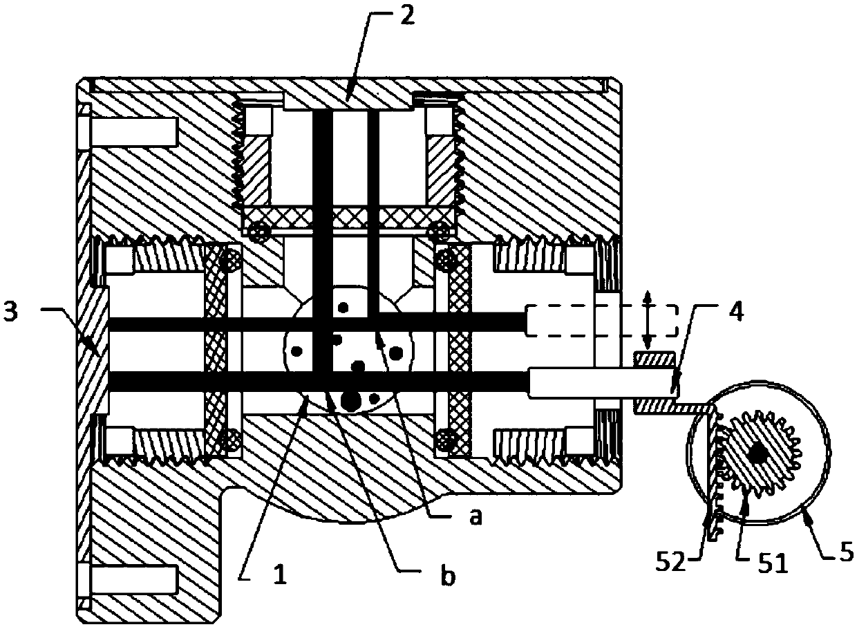
[0058] like figure 1 Shown is a schematic structural diagram of a more preferred embodiment of the fluid transparency detection device of the present invention, which includes: a detection pipeline 1, which allows the light beam to realize the incident and exit of the fluid in the tube; a laser tube 4, used to output the incident light beam ; The photodetector is used to detect the fluid exit beam.

[0059] The photodetector includes: a scattering detector 2, which is used to detect a scattered light beam; a transmission detector 3, which is used to detect a transmitted light beam; The three points of the detector, the detection pipeline, and the laser tube form a right-angle shape; the setting position of the transmission detector is on the same line as the output beam of the laser tube, and the detection pipeline is arranged between the transmission detector and the laser tube. between the laser tubes. ...

Embodiment 2

[0069] Embodiment 2 (a kind of fluid transparency detection method)

Embodiment approach

[0070] This embodiment is the first preferred embodiment of a method for detecting fluid transparency using the above-mentioned device provided by the present invention, and the method includes the following steps:

[0071] S1: Put pure fluid into the device, obtain the scattering noise floor and transmission noise floor of the equipment, and convert it into the corresponding scattered light intensity noise floor I 散射底噪 and transmitted light intensity noise floor value I 透射底噪 ;

[0072] S2: Put the fluid to be tested into the device, the laser tube outputs the laser beam, and then obtain the scattered light and transmitted light voltage signals obtained by the scattering detector and the transmission detector respectively, and convert the scattered light obtained by the scattering detector Strong I 散射 , the transmitted light intensity I obtained by the scattering detector 透射 , and get the absorbed light intensity I of the particles 吸收 ;

[0073] S3: According to the resul...


PUM


Abstract

The invention discloses a fluid transparency detection device and detection method. The detection device comprises a detection pipe, a laser tube and a photoelectric detector, the detection pipe allows incidence and emergence of the light beams in fluid in the detection pipe, the laser tube is used for outputting incidence light beams, the photoelectric detector is used for detecting emergence light beams of the fluid, and the photoelectric detector comprises a scattering detector and a transmission detector. The detection method includes the steps: acquiring a low scattering noise value and alow transmission noise value of the device, acquiring scattering light intensity I and transmission light intensity I acquired by the scattering detector, and calculating absorption intensity I of particles; acquiring total laser light intensity I; acquiring fluid transparency T. According to the detection device and the detection method, the detection accuracy of fluid transparency can be effectively improved.

Description

technical field [0001] The invention relates to the technical field of detection equipment, in particular to a fluid transparency detection device and a detection method using the device. Background technique [0002] During the operation of engines, bearings, gears, etc., in order to reduce wear and loss, it is often necessary to configure a lubricating oil system, and factors such as insufficient purity of lubricating oil and debris will bring huge disasters. In the operation process of large mechanical equipment failure, it is often a vicious circle caused by the continuous accumulation of abrasive debris in the lubricating oil. In the wear fault diagnosis system, there is a strong correlation between the damage degree of the wear parts (such as engine, rolling bearing, gear, etc.) and the particles in the lubrication system. In order to realize the detection of lubricating oil particles, a particle form detection device, such as a fluid transparency detection device, is...

Claims


Application Information

Patent Timeline
IPC IPC(8): G01N21/51G01N21/59G01N21/31
CPCG01N21/31G01N21/51G01N21/59G01N15/0211G01N15/1459G01N21/532G01N33/2858G01N33/2888G01N2015/0053G01N21/47G01N2201/025G01N2201/06113
Inventor 聂泳忠张中萍
Owner FATRI UNITED TESTING & CONTROL QUANZHOU TECH CO LTD
Why Eureka
Eureka Blog
Learn More