Eureka AIR delivers breakthrough ideas for toughest innovation challenges, trusted by R&D personnel around the world.

Steam device for fiber throwing centrifuge, ceramic fiber steam fiber throwing centrifuge and fiber making system

A ceramic fiber, spinning machine technology, applied in fiber processing, textile and papermaking, filament/thread forming, etc., can solve problems such as steam, and achieve the effect of separation and avoidance of drying

Pending Publication Date: 2019-09-27
INNER MONGOLIA HONGYANG HIGH TEMPERATURE THERMAL INSULATION MATERIAL TECH CO LTD
View PDF0 Cites 2 Cited by
  • Summary
  • Abstract
  • Description
  • Claims
  • Application Information

AI Technical Summary

Problems solved by technology

[0006] The technical task of the present invention is to address the above deficiencies, to provide a steam device for a spinning machine, a ceramic fiber steam spinning machine and a spinning system, to solve how to provide high-temperature steam when the spinning roller is spinning, so as to pass through the high-temperature The problem of steam cooling the spinning roll and providing a steamy environment for ceramic fibers

Method used


Image

  • Steam device for fiber throwing centrifuge, ceramic fiber steam fiber throwing centrifuge and fiber making system
  • Steam device for fiber throwing centrifuge, ceramic fiber steam fiber throwing centrifuge and fiber making system
  • Steam device for fiber throwing centrifuge, ceramic fiber steam fiber throwing centrifuge and fiber making system

Examples


Embodiment 1

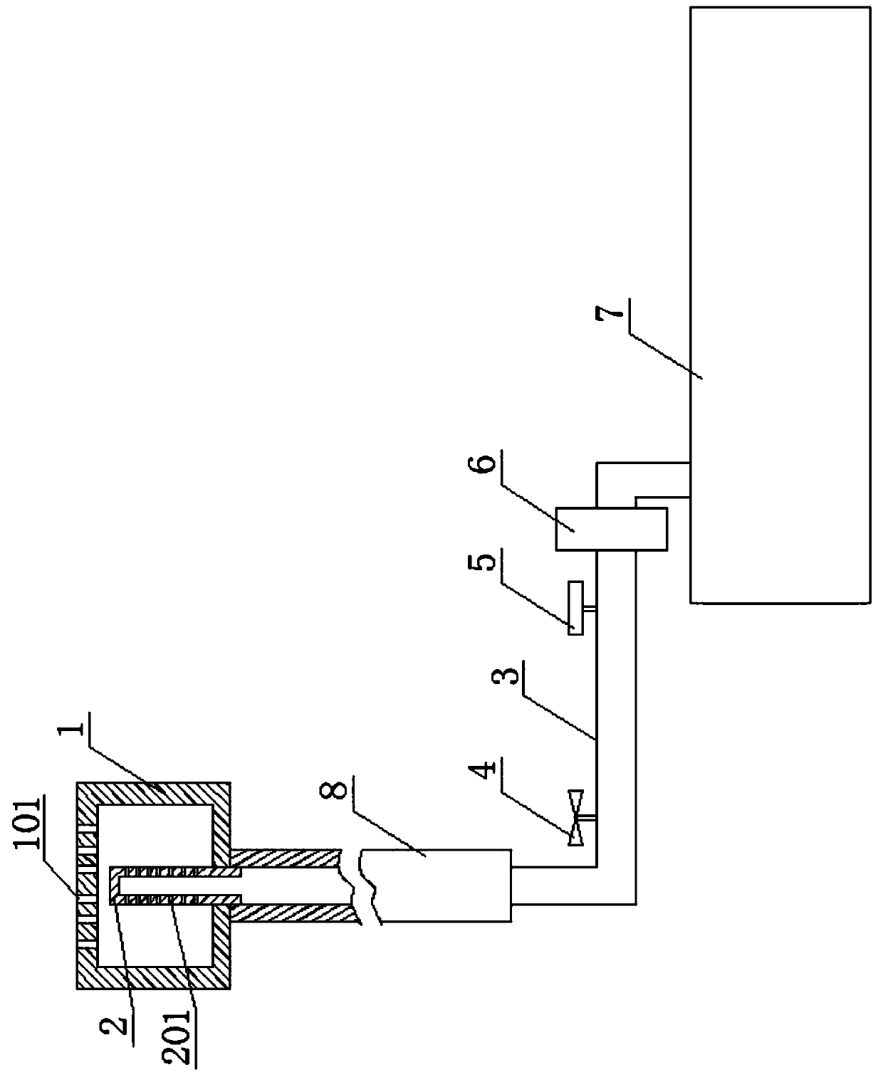
[0072] as attached figure 1 As shown, a steam device of the present invention for a spinning machine, the steam device includes a spinning head 1, a nozzle 2 and a water supply device, and is applied to a ceramic fiber spinning machine in which the spinning roller shaft 8 is a hollow shaft .

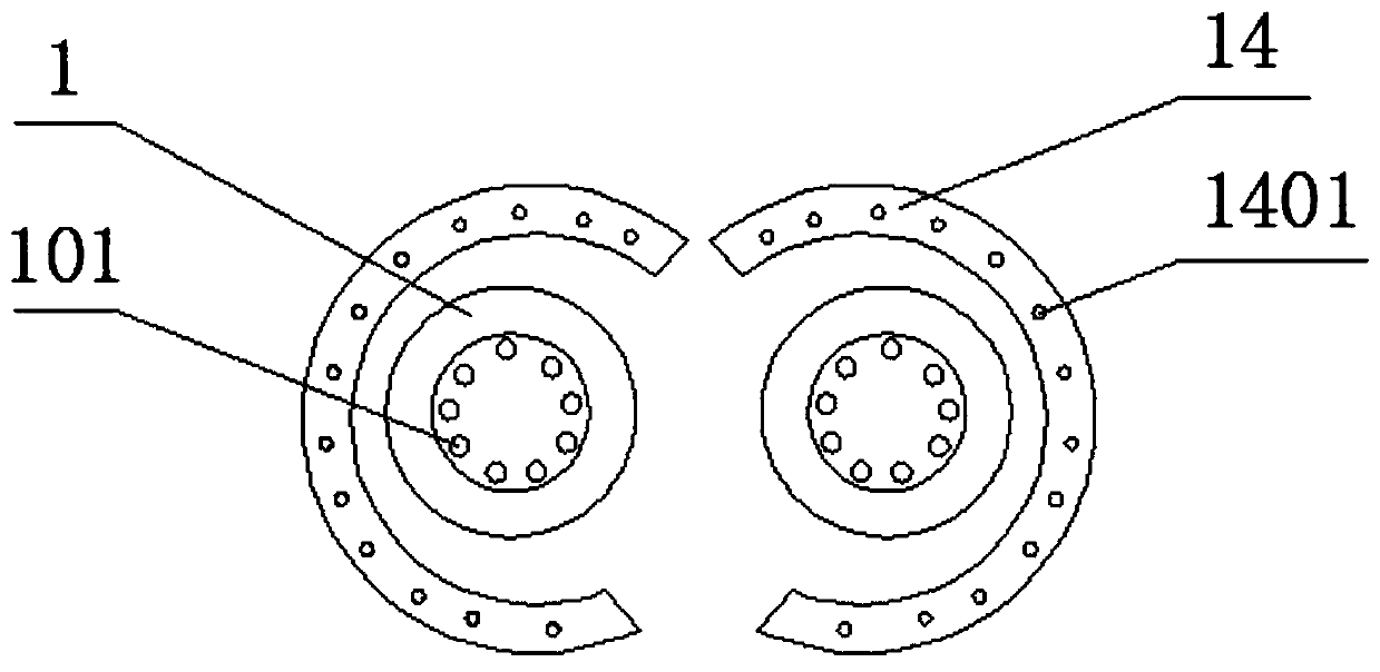
[0073] The roller head 1 is a hollow tubular structure. One of the two ends of the roller head 1 is the outlet end, and the other end is the inlet end. The outlet end of the roller head 1 is a blind end with multiple exhaust ports. The hole 101, the inlet end of the roller head 1 is an open end.

[0074] The nozzle 2 is a soft water pipe, one of the two ends of the nozzle 2 is the outlet end, and the other end is the inlet end, the outlet end of the nozzle 2 is a blind end and is built in the roller head 1, and the nozzle 2 is A plurality of drainage holes 201 are provided on the pipe wall located in the roller head 1; the inlet end of the nozzle 2 is an open end, and the inlet end of ...

Embodiment 2

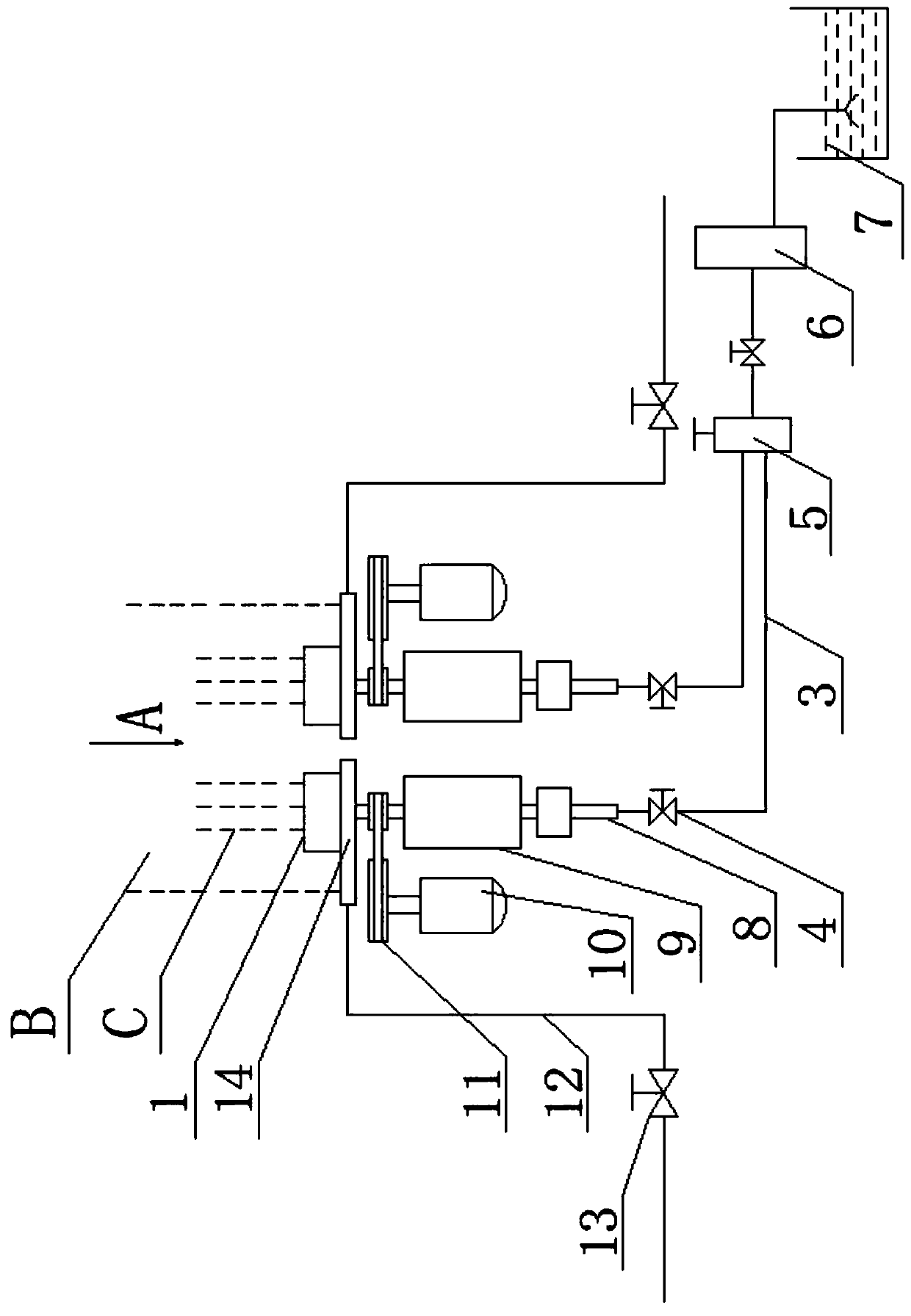
[0084] as attached figure 2 - attached Figure 5 As shown, the ceramic fiber steam spinning machine of the present invention includes a frame 23, a pair of spinning rollers, a steam device, and a spinning drive device. The steam device is the steam device disclosed in Embodiment 1 for the spinning machine.

[0085] Wherein, this pair of spinning rollers is rotatably connected on the frame 23 by the roller shaft pillow 9, and the spinning roller roller shaft 8 is a hollow shaft.

[0086] In the steam device, there are two roller heads 1, nozzle pipes 2 and water supply pipes 3 corresponding to the silk rollers one by one, and the roller head 1 is connected to the output end of the roller shaft 8 of the silk roller and communicated with the roller shaft 8 of the silk roller , the inlet end of spray pipe 2 is fixedly connected on the inner wall of the output end of spinning roller shaft 8, and nozzle pipe 2 is used as the only communication channel between spinning roller head ...

Embodiment 3

[0099] The present invention provides a ceramic fiber spinning system, comprising a melting furnace 21, a spinning machine, a cotton collector 17 and an induced draft fan. The melting furnace 21 includes a furnace body. It is used for the high-temperature ceramic fiber molten juice to flow out; the spinning machine is the spinning machine disclosed in Embodiment 2, and the spinning machine is arranged under the melting furnace 21, and two spinning rollers are arranged in parallel at the spout 22 along the horizontal direction The bottom of the ceramic fiber melt juice is used to make ceramic fibers; the cotton collector 17 includes a housing, and a cotton inlet 1701 is formed on the housing, and the cotton inlet 1701 is located at the output side of the two rejection roller heads 1, for Collect ceramic fiber; induced draft fan is used for ceramic fiber suction cotton collector 17.

[0100] In this embodiment, the cotton collector 17 housing is provided with a conveying mesh be...


PUM


Abstract

The invention discloses a steam device for a fiber throwing centrifuge, a ceramic fiber steam fiber throwing centrifuge and a fiber making system, and belongs to the field of fiber throwing centrifuges. The steam device for the fiber throwing centrifuge, the ceramic fiber steam fiber throwing centrifuge and the fiber making system aim at achieving the technical purpose of providing high-temperature steam during fiber throwing of fiber throwing rollers; the steam device structurally comprises hollow throwing roller heads, spraying pipes and a water supply device comprising water supplying pipes and a water supplying control unit, wherein several air exhausting holes are formed in one of two opposite ends of each throwing roller head, and the other ends of the throwing roller heads are used for being communicated with fiber throwing roller shafts; outlet ends of the spraying pipes are blind ends and are placed in the throwing roller heads, and several water drainage holes are formed in the portions, located in the throwing roller heads, of the walls of the spraying pipes; the water supplying pipes are communicated between the water supplying control unit and the fiber throwing roller shafts; the throwing roller heads, the spraying pipes and the water supplying pipes correspond to the fiber throwing rollers one to one. The steam fiber throwing centrifuge comprises a rack, a pair of fiber throwing rollers rotatably arranged on the rack through roller pillows, a fiber throwing driving device and the steam device. The fiber making system comprises a melting furnace, the fiber throwing centrifuge, a cotton collector and an induced draft fan.

Description

technical field [0001] The invention relates to the field of spinning machines, in particular to a steam device for spinning machines, a ceramic fiber steam spinning machine and a spinning system. Background technique [0002] With the implementation of the country's environmental protection policy and the implementation of the national brand strategy plan, all walks of life have higher and higher requirements for environmental protection and the quality of various products. The requirements for ceramic fiber cotton and ceramic fiber needle-punched blankets in the market are getting higher and higher, especially for national key projects, as well as military and scientific research projects. Higher requirements are put forward for the length, thickness, flexibility, and content of slag balls. The common three-roller and two-roller spinning machines and processes in the ceramic fiber production industry cannot produce fiber cotton and blankets that can meet the needs of the ...

Claims


Application Information

Patent Timeline
Patent Type & Authority Applications(China)
IPC IPC(8): D01D5/18D01F9/08D01D13/00D01D13/02
CPCD01D5/18D01F9/08D01D13/00D01D13/02
Inventor 郑志永孙选吕光耀
Owner INNER MONGOLIA HONGYANG HIGH TEMPERATURE THERMAL INSULATION MATERIAL TECH CO LTD
Why Eureka
Eureka Blog
Learn More