Variable offset spine fixation system and method

A technology of spinal rods and anchors, applied in the field of orthopedics, which can solve the problems that bone anchors are removed from the vertebral bodies where they are implanted, and surgeons cannot insert rods.

Inactive Publication Date: 2012-09-19
SYNTHES GMBH
View PDF7 Cites 2 Cited by
  • Summary
  • Abstract
  • Description
  • Claims
  • Application Information

AI Technical Summary

Problems solved by technology

When strong rod insertion instruments are available for rod and screw construction systems, the surgeon often cannot fully insert the rod into the anchor seat without pre-bending and re-bending the rod to the point where it could weaken the rod
Also, applying too much force during full insertion of the spinal rod may dislodge one or more of the implanted bone anchors from the vertebral body in which they are implanted.

Method used


Image

  • Variable offset spine fixation system and method
  • Variable offset spine fixation system and method
  • Variable offset spine fixation system and method

Examples


Embodiment Construction

[0014] Certain terms used in the following description are for convenience only and not for limitation. The words "right", "left", "lower" and "upper" indicate directions in the drawings to which reference is made. The words "medial" or "distal" and "lateral" or "proximal" refer to directions toward and away from, respectively, the geometric center of the spinal fixation system and its associated components. The words "front", "rear", "above", "below" and related words and / or phrases refer to preferred positions and orientations in the human body to which reference is made and are not limiting. The term includes the above words, derivatives thereof and words of similar import.

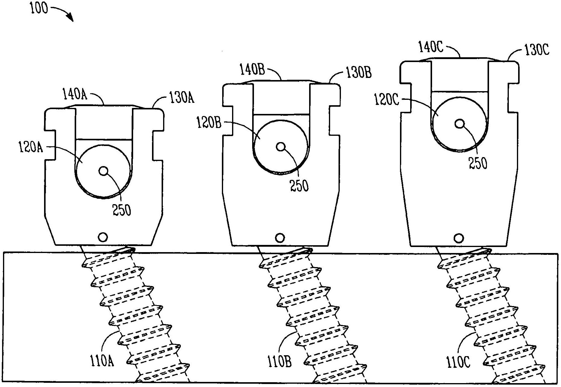
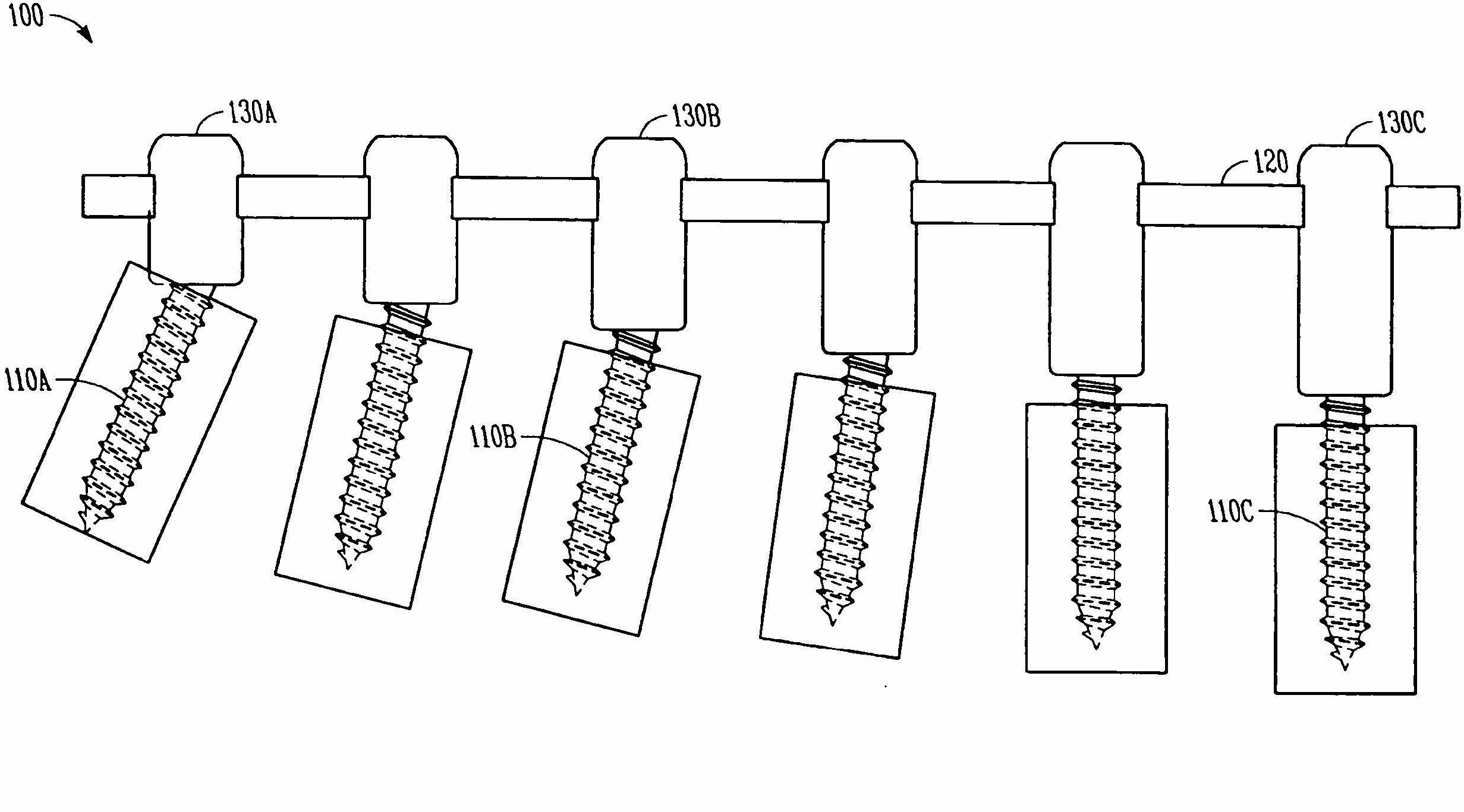
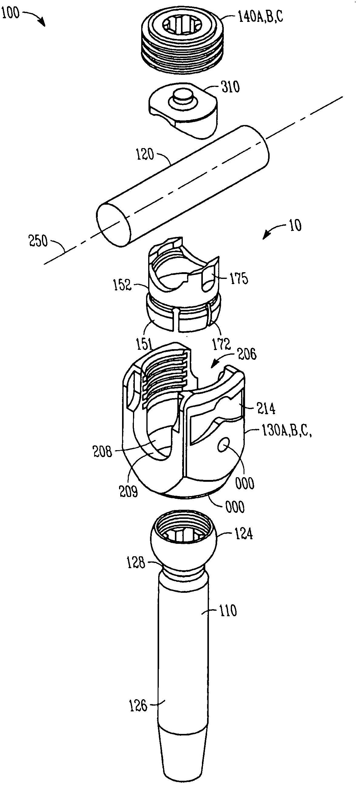
[0015] refer to figure 1 and 2 , a spinal fixation system 100 is provided that includes a plurality of bone anchors 110A, 110B, 110C, a plurality of anchor receptacles 130A, 130B, 130C, a plurality of collets 152 and a plurality of locking caps 140A, 140B, 140C. System 100 also preferably includes ...


PUM


Abstract

A minimally invasive system and method for coupling a spinal rod to a plurality of bone anchors implanted into a plurality of vertebral bodies. A plurality of bottom-loading polyaxial anchor seat assemblies (130A, 130B, 130C having different vertical heights are chosen to pop over the heads (124) of the implanted bone anchors (110A, 110B, 110C ) and a spinal rod (120) is more easily introduced and secured to the bone anchors. The variety of different heights that characterize the plurality of polyaxial anchor seat assemblies allows a surgeon to intraoperatively choose the appropriate offset for a particular spinal level during spinal corrections.

Description

Background technique [0001] In some spinal surgery procedures it is desirable to have a minimum of surgical steps during posterior screw and rod placement. Current top-loading polyaxial pedicle screw systems (where the bone anchor is manually loaded down through the top of the anchor seat prior to surgery, or more commonly pre-assembled the combination) typically Multiple surgical steps are required. These steps may include implanting a plurality of polyaxial screw and anchor seat assemblies, inserting a spinal rod into the plurality of screw and anchor seat assemblies, inserting a locking cap into each screw and anchor seat assembly, and tightening the locking cap to each screw and anchor seat assembly for locking the structure. Due to the anatomical position of the bone anchor, the nature of the anatomical correction required, the less than optimal stem bend, and other factors that complicate the complete reduction of the stem into the anchor seat, the placement of the ste...

Claims


Application Information

Patent Timeline
Patent Type & Authority Applications(China)
IPC IPC(8): A61B17/70
CPCA61B17/7037A61B17/7032A61B17/70A61B17/86
Inventor R·P·雅各布E·麦克迪维特J·卡波佐利T·基尔
Owner SYNTHES GMBH
Why Eureka
Try Eureka