Post-Operatively Adjustable Spinal Fixation Devices

a spinal fixation device and post-operative adjustment technology, applied in the field of medical devices, can solve the problems of minor spinal injuries that can be debilitating to patients, major spinal injuries can be catastrophic, and patients lose the ability to bear weight or permit flexibility

Active Publication Date: 2019-07-18
NUVASIVE
View PDF0 Cites 6 Cited by
  • Summary
  • Abstract
  • Description
  • Claims
  • Application Information

AI Technical Summary

Benefits of technology

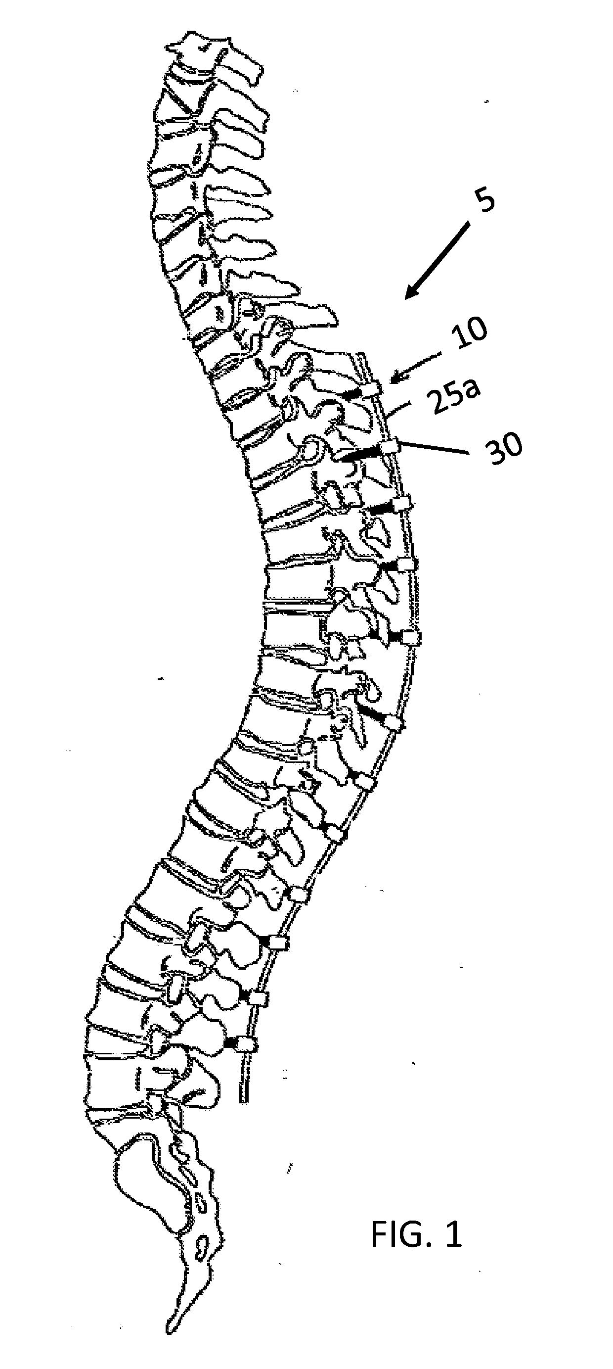
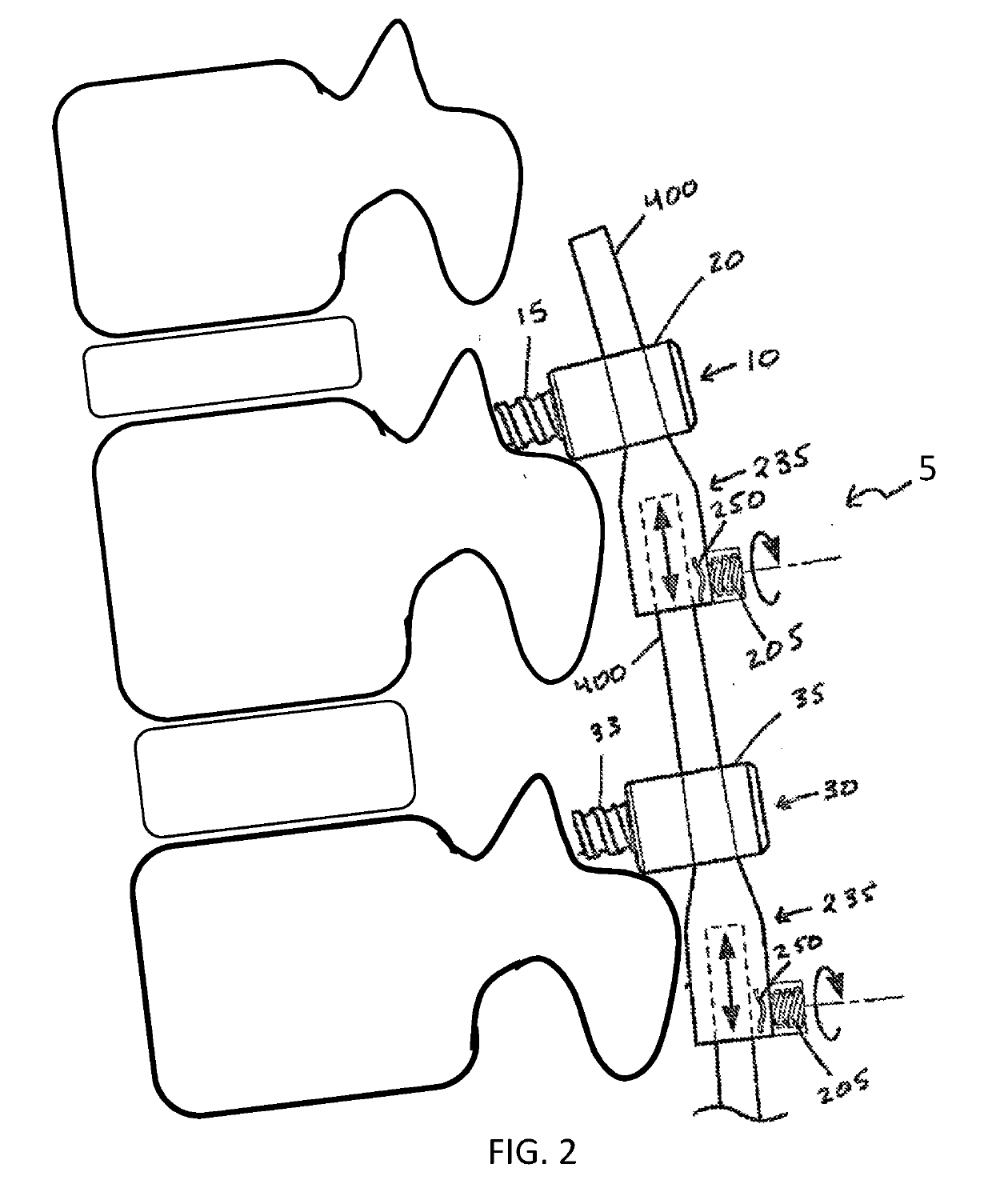
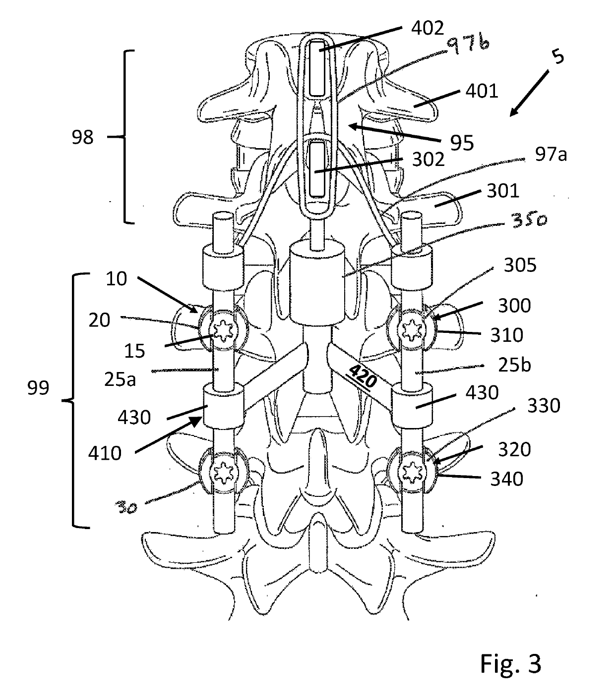
[0010]The problems noted above, as well as potentially others, can be addressed in this disclosure by a system for spinal fixation with a non-rigid portion, e.g., a soft zone, at one or more of the caudal or cephalad terminus. Various devices and techniques are described herein for transition from a rigid fixation device to a less rigid, more flexible support structure applied to a “soft zone” that may help share the stress created on the spinal levels caused by the fixed levels below and / or above. In some embodiments, the soft zone is provided by terminating the spinal fixation system with one or more of a flexible tether assembly, a telescoping rod, or a dampening rod.

Problems solved by technology

Even minor spinal injuries can be debilitating to the patient, and major spinal injuries can be catastrophic.
The loss of the ability to bear weight or permit flexibility can immobilize the patient.
Even in less severe cases, small irregularities in the spine can put pressure on the nerves connected to the spinal cord, causing devastating pain and loss of coordination.
Traumatic and catastrophic conditions may occur as a generally sudden shifting of the vertebral body immediately cephalad to the upper end instrumented vertebra and can lead to sudden changes in spinal alignment with marked symptoms noted by the patient.
Adjacent segment pathology and more specifically PJK can be a result of excess strain and stress on the proximal instrumented spinal segment which is then at least partially transferred to the bone structures, disc, ligaments and other soft tissues, causing a loss of normal structural integrity and mechanical properties.
Another theory is that the rigidity of the screw and rod construct causes the problem in that the transition from a motion-restrained segment to a motion-unrestrained segment is too much for the non-instrumented (unrestrained) segment to handle over time.

Method used


Image

  • Post-Operatively Adjustable Spinal Fixation Devices
  • Post-Operatively Adjustable Spinal Fixation Devices
  • Post-Operatively Adjustable Spinal Fixation Devices

Examples


Embodiment Construction

[0029]Illustrative embodiments of a system for spinal fixation, parts, and methods for use thereof, are described below. In the interest of clarity, not all features of an actual implementation are described in this specification. It will of course be appreciated that in the development of any such actual embodiment, numerous implementation-specific decisions must be made to achieve the developers' specific goals, such as compliance with system-related and business-related constraints, which will vary from one implementation to another. Moreover, it will be appreciated that such a development effort might be complex and time-consuming, but would nevertheless be a routine undertaking for those of ordinary skill in the art having the benefit of this disclosure. The system for spinal fixation, parts, and methods for use thereof disclosed herein boasts a variety of inventive features and components that warrant patent protection, both individually and in combination.

[0030]While various ...


PUM

PropertyMeasurementUnit
timeaaaaaaaaaa
timeaaaaaaaaaa
compressibleaaaaaaaaaa

Abstract

A system for spinal fixation with a non-rigid portion at least one of the caudal or cephalad terminus. Various devices and techniques are described for transition from a rigid fixation construct to a less rigid support structure applied to a “soft zone” that helps share the stress created on the spinal levels caused by the fixed levels below. In some embodiments, the soft zone is provided by terminating the construct with one of a flexible tether or a dampening rod.

Description

CROSS-REFERENCES[0001]This application is a continuation-in-part of U.S. patent application Ser. No. 15 / 432,647 filed Feb. 14, 2017, which is a continuation of International Application PCT / US17 / 17700, filed 13 Feb. 2017 that claims priority to U.S. Patent Application No. 62 / 294,975, filed on 12 Feb. 2016, the contents of which are entirely incorporated herein by reference.BACKGROUNDField[0002]The present disclosure relates generally to medical devices, and specifically to surgical instruments and methods for performing spinal procedures.[0003]The spine is critical in human physiology for mobility, support, and balance. The spine protects the nerves of the spinal cord, which convey commands from the brain to the rest of the body, and convey sensory information from the nerves below the neck to the brain. Even minor spinal injuries can be debilitating to the patient, and major spinal injuries can be catastrophic. The loss of the ability to bear weight or permit flexibility can immobi...

Claims


Application Information

Patent Timeline
Patent Type & Authority Applications(United States)
IPC IPC(8): A61B17/70
CPCA61B17/7016A61B17/7043A61B17/7053A61B2017/00876A61B17/7052A61B17/7004A61B17/7022A61B17/7056A61B17/7065A61B17/7067B29C70/44
Inventor BANNIGAN, SHAEFFERDOOSE, JUSTIN
Owner NUVASIVE
Why Eureka
Try Eureka