
Forward spinning mechanism for cylindrical member

A cylindrical part and spinning technology, applied in the field of spinning processing, can solve the problems of easy instability of the tail end material, prolong the production cycle, low work efficiency, etc., to improve the material utilization rate, increase the effective forming section, optimize the Effect of contact state

Active Publication Date: 2014-06-18
NORTHWESTERN POLYTECHNICAL UNIV
View PDF7 Cites 0 Cited by
  • Summary
  • Abstract
  • Description
  • Claims
  • Application Information

AI Technical Summary

Problems solved by technology

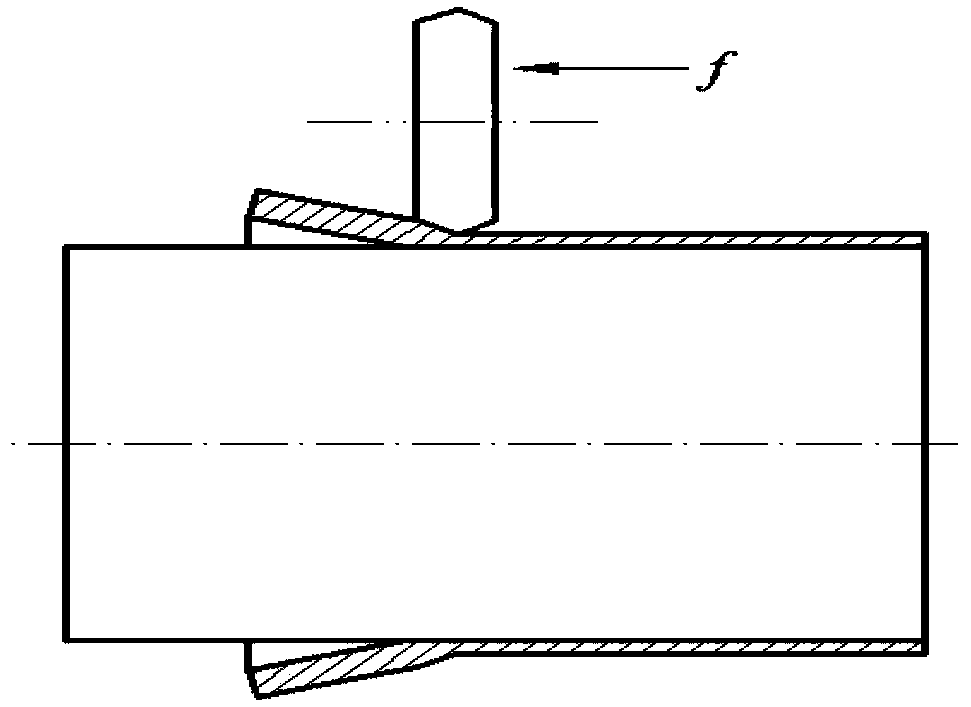
[0004] At present, in the prior art, in addition to reserving a certain machining allowance at the tail end of the blank and processing it with a machine after spinning, the processing method for the bell mouth produced at the end of the forward spinning of the cylindrical part is In addition to the cutting method, there is also a multi-pass shrinking spinning process to shrink and eliminate the bell mouth at the end of the workpiece after the spinning is completed, but this multi-pass shrinking process will greatly extend the production cycle. Low working efficiency, and when shrinking the bell mouth at the tail end of the workpiece, the material at the tail end is prone to instability, and in severe cases, it will wrinkle or break
In summary, the existing technology has not yet proposed a method that can effectively and specifically suppress the positive spinning of the tail end of the cylindrical part.

Method used


Image

  • Forward spinning mechanism for cylindrical member
  • Forward spinning mechanism for cylindrical member
  • Forward spinning mechanism for cylindrical member

Examples


Embodiment Construction

[0033] This embodiment is a forward spinning mechanism for cylindrical parts. The blank of the cylindrical part is an LF21M aluminum alloy pipe with an outer diameter of 106 mm, an inner diameter of 100 mm, a pipe wall thickness of 3 mm, and an axial length of 500 mm. During the spinning process of this implementation case, the thickness reduction of the blank is 1.2mm.

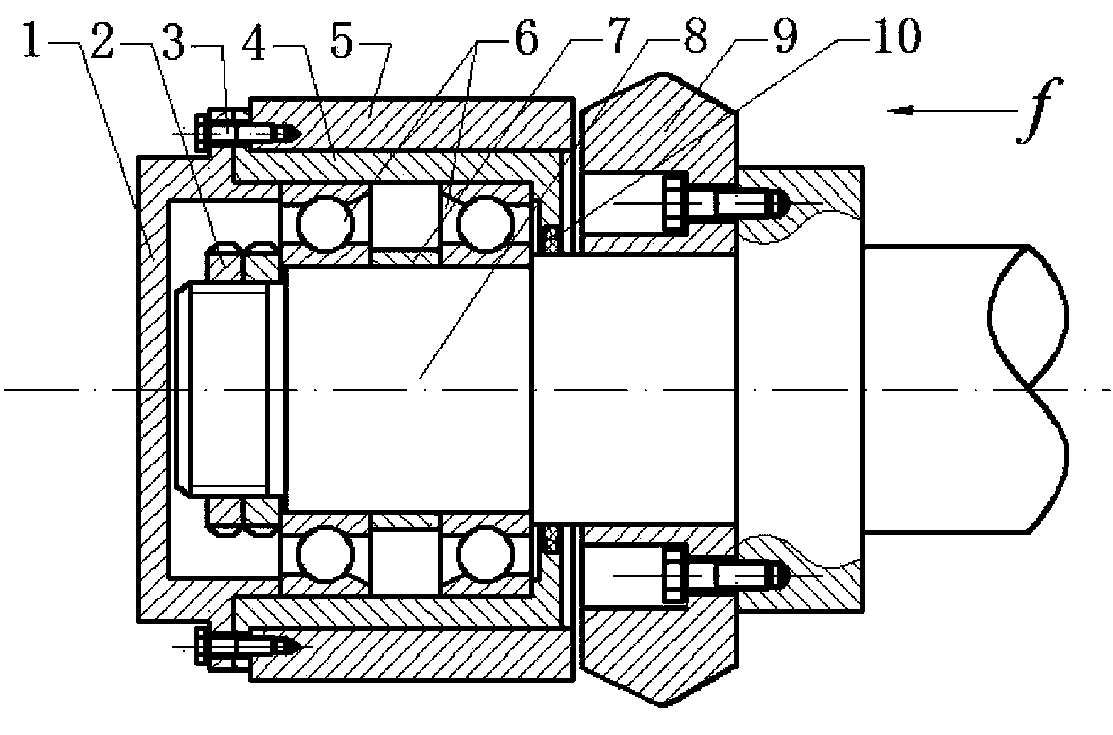
[0034] The mechanism used in this embodiment to prevent the forward spinning of the aluminum alloy cylindrical part to press the bell mouth at the tail end includes a rotary mandrel 8, a rotary wheel 9, a pressure ring 5, a fixed sleeve 4, a sleeve 7, a pair of angular contact bearings 6 and Bearing cover 1.

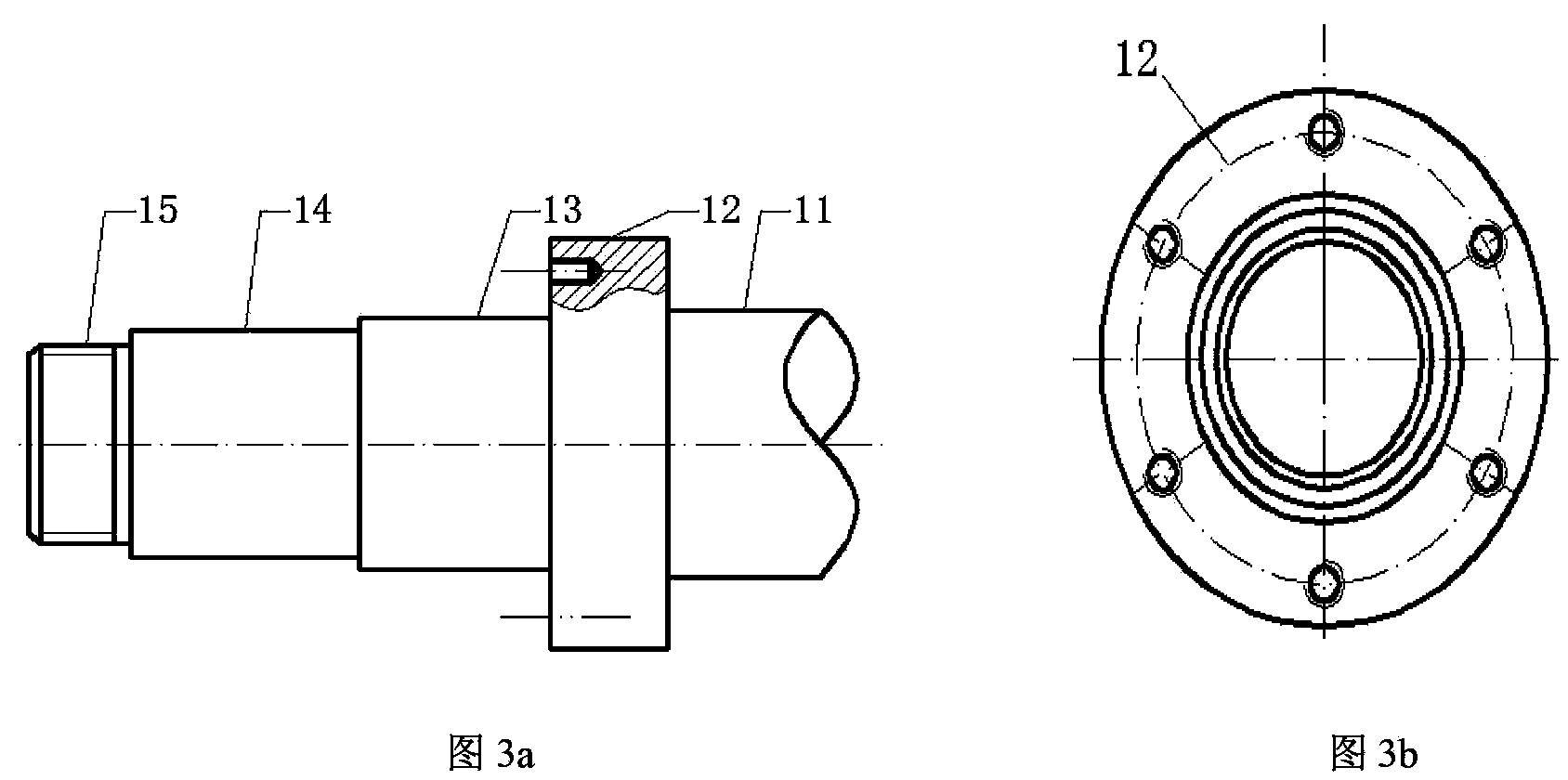
[0035] The rotary wheel mandrel 8 is a five-stage stepped shaft. One end of the wheel mandrel 8 is a fastening nut installation section 15, and the fastening nut installation section 15 has external threads. The other end of the wheel mandrel 8 is the wheel seat matching section 11 that the wheel man...


PUM

PropertyMeasurementUnit
lengthaaaaaaaaaa
diameteraaaaaaaaaa
diameteraaaaaaaaaa

Abstract

The invention discloses a forward spinning mechanism for cylindrical member. A spinning wheel seat of the spinning machine is fitted on the spinning wheel seat fitting section of a spinning wheel spindle; a spinning wheel is mounted on the spinning wheel mounting section of the spinning wheel spindle and fixed on the end face of the positioning boss of the spinning wheel spindle; a fixation clamp plate is fitted on a press ring mounting section via a pair of angular contact bearings and a press ring is fitted on the outer circumference of the fixation clamp plate; a set nut is fitted on a set nut mounting section; and the spinning wheel spindle, the spinning wheel and the press ring have coincident axial lines. According to the forward spinning mechanism provided by the invention, the press ring freely rotates relative to the spinning wheel and the spinning wheel spindle to reduce friction between the blank and the press ring and exert inward radial extruding effects on the blank bulging in front of the spinning wheel during the spinning process so as to limit outward radial flow of material in front of the spinning wheel, promote axial flow of the material during processing, inhibit diameter expansion of the blank in the non-spinning region, make deformation of the cylindrical member smooth during the forming process and finally prevent bell mouth generation at the tail end of the blank at the late stage of spinning.

Description

technical field [0001] The invention belongs to the field of spinning processing, in particular to a forward spinning mechanism for cylindrical parts. Background technique [0002] Forward spinning of cylindrical parts is a continuous local plastic forming method for forming high-precision thin-walled cylindrical parts. It has the characteristics of small spinning force, high production efficiency and low labor intensity. In the forward spinning process of cylindrical parts, one end of the cylindrical blank is fixed to the mandrel by the clamping device and the axis of the cylindrical blank coincides with the axis of the mandrel, and the active rotation of the mandrel drives the synchronous rotation of the billet and the mandrel. The rotary wheel makes a linear feed motion to the other end of the cylindrical blank along the axial direction of the mandrel, so that the thickness of the cylindrical blank is reduced and the length is elongated to form a thin-walled long cylindri...

Claims


Application Information

Patent Timeline
Patent Type & Authority Patents(China)
IPC IPC(8): B21D22/16
Inventor 詹梅石丰翟华东杨合
Owner NORTHWESTERN POLYTECHNICAL UNIV
Learn More