A cross-tube heat exchanger and a pulse tube refrigerator with the heat exchanger

A technology of tubular heat exchangers and thin tubes, which is applied in the direction of refrigerators, indirect heat exchangers, heat exchanger types, etc., can solve the problem of restricting the development of high-power pulse tube refrigerators and the uneven inlet temperature of the hot end of the regenerator , Uneven temperature distribution at the inlet and outlet, etc., to alleviate the uneven temperature distribution, improve the uneven temperature distribution, and the effect of simple and reliable structure

Active Publication Date: 2022-02-11
ZHEJIANG UNIV
View PDF4 Cites 0 Cited by
  • Summary
  • Abstract
  • Description
  • Claims
  • Application Information

AI Technical Summary

Problems solved by technology

[0003] At present, the main problems faced by high-power pulse tube refrigerators are: impedance matching between compressor and cold head, insufficient heat transfer capacity under alternating flow, uneven temperature distribution of regenerator, etc., which limit the high-power pulse tube refrigerator. Development of refrigerators
At present, the shell-and-tube heat exchanger widely used in pulse tube refrigerators still has the problem of insufficient heat transfer capacity, and the temperature at the hot end of the regenerator is much higher than normal temperature; The uneven temperature at the inlet of the hot end of the regenerator is a possible cause of the uneven temperature distribution in the middle of the regenerator

Method used


Image

  • A cross-tube heat exchanger and a pulse tube refrigerator with the heat exchanger
  • A cross-tube heat exchanger and a pulse tube refrigerator with the heat exchanger
  • A cross-tube heat exchanger and a pulse tube refrigerator with the heat exchanger

Examples


Embodiment

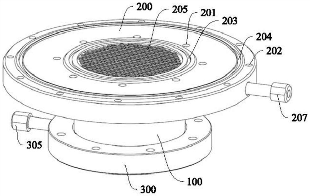
[0035] see Figure 1 to Figure 4 , the cross-tube heat exchanger in this embodiment includes a cylinder body 100 and an upper flange 200 and a lower flange 300 that are hermetically installed at both ends of the cylinder body 100 .

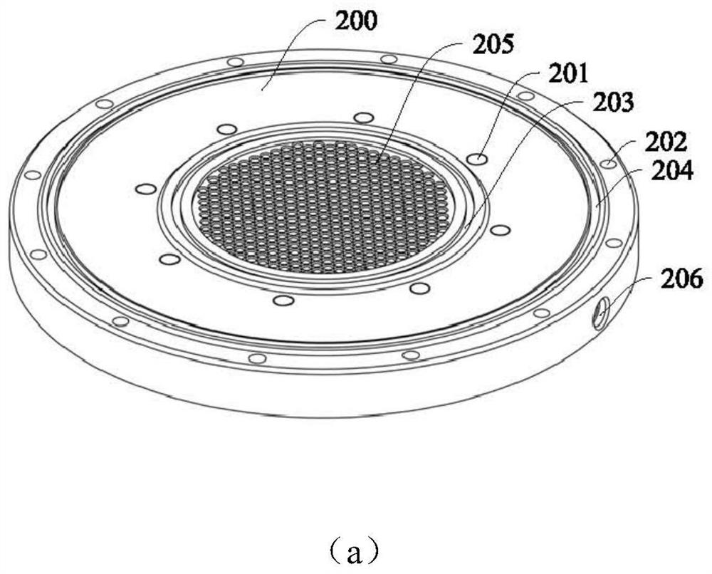
[0036] The upper flange 200 is provided with circumferentially arranged threaded holes 201 and 202 for connecting the next stage component (regenerator) and the vacuum cover. A sealing ring groove 203 and a sealing ring groove 204 for sealing the next-stage components are respectively provided adjacent to the threaded hole circumferential direction. An upper mounting plate 205 is arranged in the middle of the upper flange 200, and a plurality of mounting holes for thin heat exchange tubes are regularly opened. The side of the upper flange 200 has an outlet channel 206 connected to the middle through hole, and an outlet pipe 207 is sealed inside it.

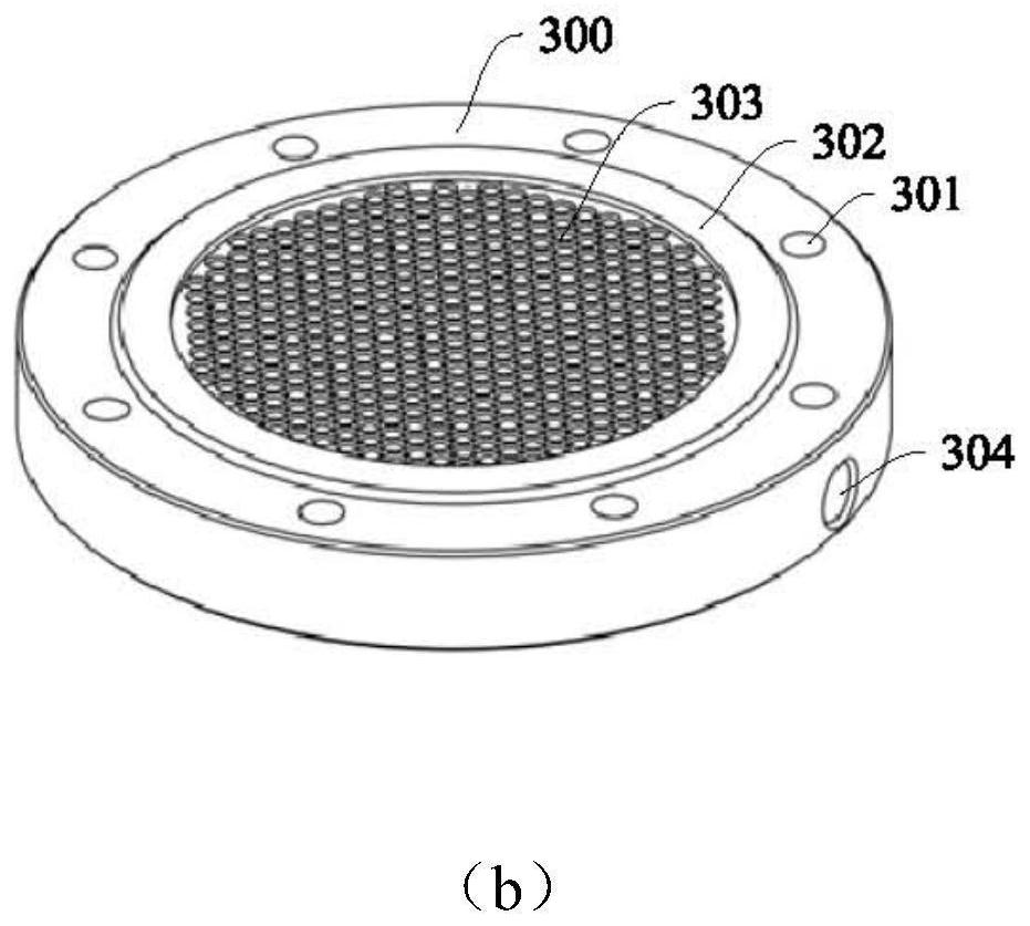
[0037] The lower flange 300 is provided with circumferentially arranged threaded holes 301 and a...


PUM


Abstract

The invention relates to a cross-tube heat exchanger and a pulse tube refrigerator with the heat exchanger, belonging to the technical field of low-temperature refrigeration. It includes a cylinder body and an upper flange and a lower flange respectively arranged at the upper and lower ends of the cylinder body. It is characterized in that a number of thin heat exchange tubes are arranged in the cylinder body, and the heat exchange thin tubes are connected to form a first A medium channel, a second medium channel is formed between the tube wall of the thin heat exchange tube and the inner wall of the cylinder. Increase the heat exchange area and enhance the heat exchange efficiency by using thin heat exchange tubes. At the same time, provide gas lateral flow channels, introduce radial flow on the gas working medium side, and transform the original heat transfer form of the gas working medium in the heat exchanger. For the coupling of heat conduction and gas self-mixing, the radial temperature distribution of the working fluid in the heat exchanger and the outlet is more uniform, and the uneven temperature distribution at the inlet of the regenerator is alleviated, and finally the problem of non-uniform temperature of the regenerator is optimized to reduce heat recovery The loss of the device is reduced, and the cooling performance of the whole machine is finally improved.

Description

technical field [0001] The invention relates to the technical field of low-temperature refrigeration, in particular to a cross-tube heat exchanger and a pulse tube refrigerator with the heat exchanger. Background technique [0002] As a low-temperature refrigerator, the pulse tube refrigerator has become a research hotspot in the field of cryogenic refrigerators due to its characteristics of no moving parts at the cold end, simple structure, small mechanical vibration, high reliability at low temperatures, and long working life. widely. [0003] At present, the main problems faced by high-power pulse tube refrigerators are: impedance matching between compressor and cold head, insufficient heat transfer capacity under alternating flow, uneven temperature distribution of regenerator, etc., which limit the high-power pulse tube refrigerator. Development of refrigerators. [0004] For the Stirling-type pulse tube refrigerator with a hundred-watt-level cooling capacity in the l...

Claims


Application Information

Patent Timeline
Patent Type & Authority Patents(China)
IPC IPC(8): F25B9/14F28D7/16F28F9/18F28F9/26
CPCF25B9/145F28D7/163F28F9/18F28F9/268
Inventor 韦涛植晓琴林锦城邱利民陶希军
Owner ZHEJIANG UNIV
Why Eureka
Try Eureka