LED driver board constant current test fixture and its test method
A technology of LED driving and testing tooling, applied in the direction of electronic circuit testing, etc., can solve the problems of inconvenient testing efficiency and low efficiency, and achieve the effect of simple structure, easy operation and high reliability
- Summary
- Abstract
- Description
- Claims
- Application Information
AI Technical Summary
Problems solved by technology
Method used
Image

Examples
Embodiment Construction
[0016] Embodiments of the present invention are described in detail below in conjunction with accompanying drawings:
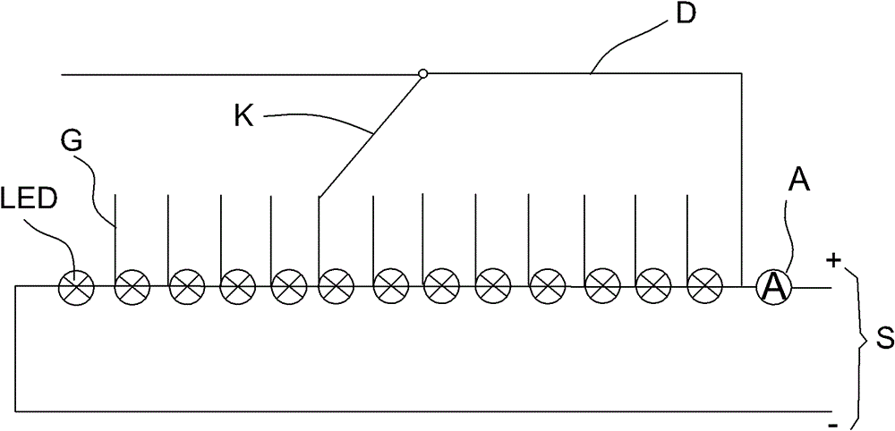
[0017] Such as figure 1 As shown, the LED driver board constant current test tooling of the present invention includes: a current input terminal S, 13 LEDs are connected in series with the positive pole of the current input terminal S, and each LED is connected with a fixed contact G, which is connected to the positive pole of the current input terminal S. The guide rail D connected to the current input terminal S, and the adjustable contact K, one end of the adjustable contact K is slidably fixed on the guide rail D, and the other end is connected to the fixed contact G of any one of the LEDs, The positive and negative poles of the current input terminal S are connected to the positive and negative poles of the driving board.
[0018] Wherein, the number of the LEDs can be set according to different numbers of LEDs to meet the needs of different users.
[0...
PUM
 Abstract
Description
Claims
Application Information
 - R&D
- Intellectual Property
- Life Sciences
- Materials
- Tech Scout
- Unparalleled Data Quality
- Higher Quality Content
- 60% Fewer Hallucinations
Browse by: Latest US Patents, China's latest patents, Technical Efficacy Thesaurus, Application Domain, Technology Topic, Popular Technical Reports.
© 2025 PatSnap. All rights reserved.Legal|Privacy policy|Modern Slavery Act Transparency Statement|Sitemap|About US| Contact US: help@patsnap.com