Supercharge Your Innovation With Domain-Expert AI Agents!

Analog engine pressurization regulating signal generating method

A technology of boost regulation and signal generation module, applied in engine control, combustion engine, machine/engine, etc., to achieve the effect of good versatility, simple hardware structure and high precision

Inactive Publication Date: 2015-05-27
BEIJING INSTITUTE OF TECHNOLOGYGY
View PDF5 Cites 0 Cited by
  • Summary
  • Abstract
  • Description
  • Claims
  • Application Information

AI Technical Summary

Problems solved by technology

At present, there is no relevant patent for simulating the generation of engine boost regulation signal under CAN bus communication

Method used


Image

  • Analog engine pressurization regulating signal generating method
  • Analog engine pressurization regulating signal generating method
  • Analog engine pressurization regulating signal generating method

Examples


example example 1

[0026] refer to figure 1

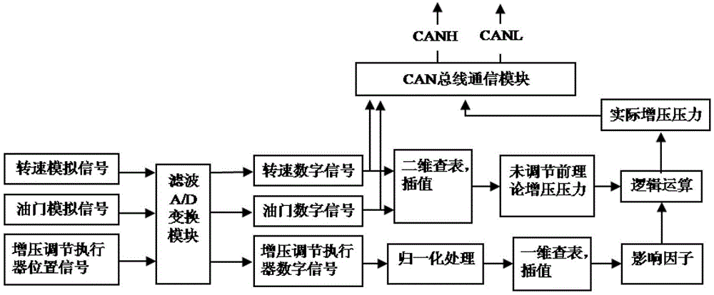
[0027] A method for generating an analog engine boost regulation signal, comprising the following steps:

[0028] 1) Connect the analog signal of the engine speed, the analog signal of the throttle, and the position signal of the booster adjustment actuator to the analog input channel of the ADC (analog-to-digital converter) of the single-chip microcomputer, and perform filtering and A / D conversion processing. The output range of speed and throttle signal is 0~5V, the analog signal of speed is mapped to 600~3000r / min through A / D conversion, and the analog signal of throttle is mapped to the range of 5%~100% through A / D conversion.

[0029] 2) According to the pre-set two-dimensional data table of supercharging pressure, the input variables are speed and throttle, and the two-dimensional table lookup and interpolation are performed based on the speed and the size of the throttle to obtain the current speed and boost pressure under the throttle Press...

Embodiment 2

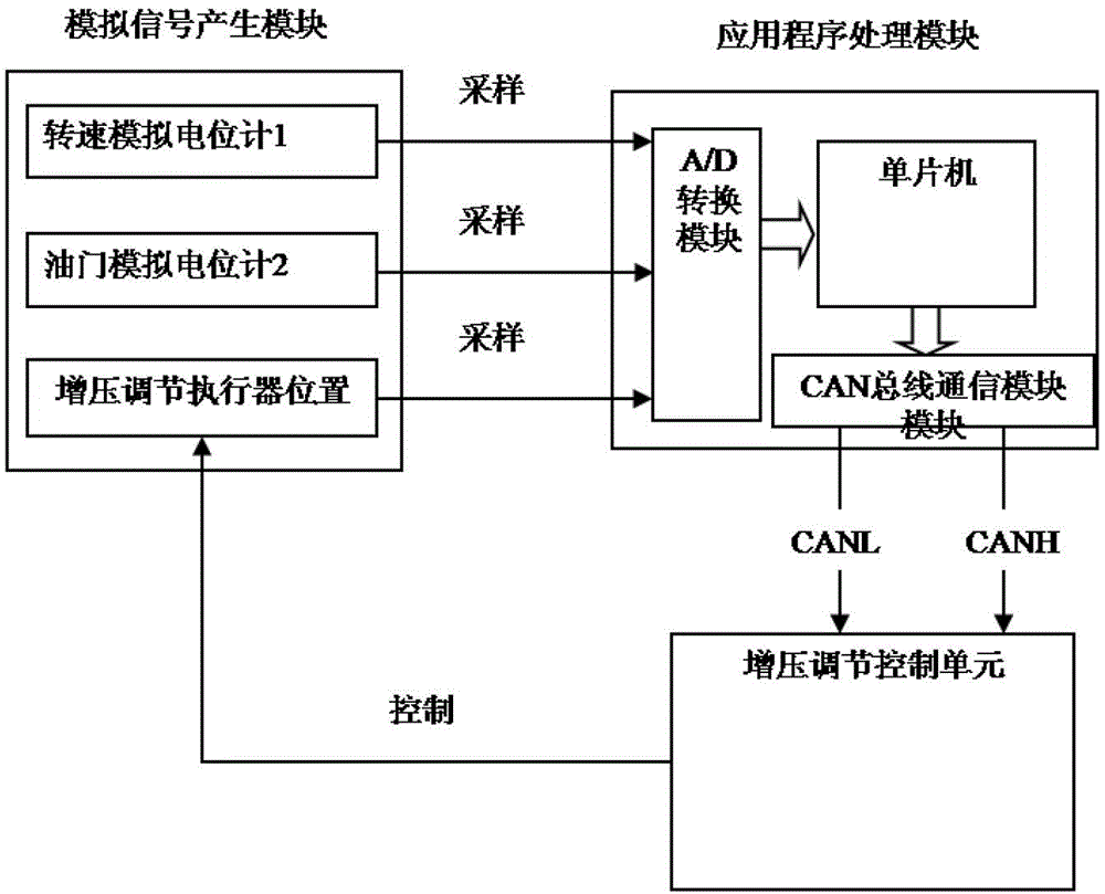
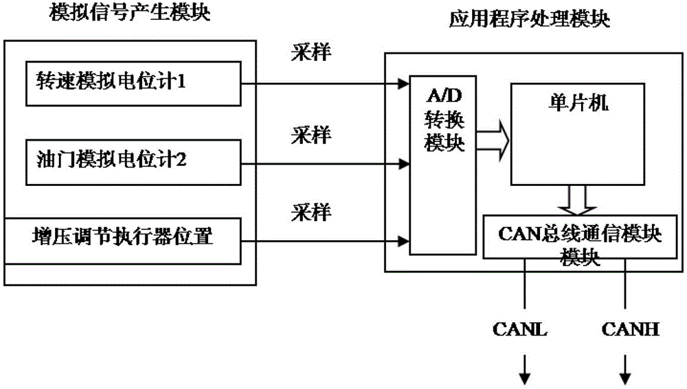
[0041] refer to Figure 2 ~ Figure 3 , the rotational speed analog signal generation module, the throttle analog signal generation module, and the pressure boost adjustment actuator position signal generation module are analog signal generation modules, which respectively use the rotational speed potentiometer 1, the throttle potentiometer 2 and the actuator position slide wire rheostat to generate Analog signals of engine speed, throttle, booster actuator position;

[0042] The analog-to-digital converter, the two-dimensional table look-up module, the normalization module, the logical operation module and the CAN bus communication module are the application program modules, which convert this method into corresponding program codes and run on the single-chip microcomputer, the single-chip microcomputer is Infineon XC167, The input voltage range of the analog-to-digital conversion channel is 0-5V, so the input power supply of speed potentiometer 1, throttle potentiometer 2, an...


PUM


Abstract

The invention relates to an analog engine pressurization regulating signal generating method. The method includes the following steps: (1) collecting rotating speed, accelerator signals, pressurization regulating actuator position signals of an analog engine and carrying out filtering and analog to digital (A / D) conversion; (2) carrying out two-dimensional lookup table interpolation according to the rotating speed and an accelerator, and obtaining theoretical pressurizing pressure of the current rotating speed and the accelerator; (3) carrying out normalization processing on digital quantity of the pressurization regulating actuator position signals; (4) carrying out one-dimensional lookup table interpolation according to pressurization regulating actuator relative position signals, and obtaining impact factors of a pressurization regulating actuator on the pressurizing pressure under a current state; (5) using the theoretical pressurizing pressure before regulation to be multiplied by the impact factors for obtaining actual pressurizing pressure; and (6) using a controller area network (CAN) bus communication module to output the signals of the rotating speed, the accelerator and the actual pressurizing pressure. The method is accurate in generated signals and good in generality, and is effectively applied to a testing system of an engine pressurization regulating control unit.

Description

technical field [0001] The invention relates to the technical field of electronically controlled engine signal simulation generation, in particular to a method for generating a simulation engine boost adjustment signal. Background technique [0002] In the research of modern automobile engine management system, the increasingly complex functional requirements and strict regulations make the development process of ECU (Electronic Control Unit) hardware and software more and more complicated, so a strict and efficient development method is required to Guarantee the quality of product-level ECU. In order to improve the efficiency and accuracy of product development, the development of automotive electronic systems proposes a modern model-based development process—V model development process, which ensures that every step of the development process can be verified in time by developers. Before the product goes on the market, it is necessary to conduct a comprehensive and compre...

Claims


Application Information

Patent Timeline
Patent Type & Authority Patents(China)
IPC IPC(8): F02D23/00
CPCY02T10/12
Inventor 刘兴华糜思富张海民许家全赵锐娜
Owner BEIJING INSTITUTE OF TECHNOLOGYGY
Features
  • R&D
  • Intellectual Property
  • Life Sciences
  • Materials
  • Tech Scout
  • Unparalleled Data Quality
  • Higher Quality Content
  • 60% Fewer Hallucinations
Learn More