Gear of workpiece rotating stamping die

A technology for stamping dies and workpieces, applied in the field of metal processing tools, can solve problems such as low efficiency, restrict the development of enterprises, increase labor costs of enterprises, etc., and achieve the effect of improving efficiency

Active Publication Date: 2014-09-24
HUZHOU IRON FORCE METAL PROD
View PDF8 Cites 0 Cited by
  • Summary
  • Abstract
  • Description
  • Claims
  • Application Information

AI Technical Summary

Problems solved by technology

Manual operation has the following defects: one is that the accuracy is not high
Second, inefficiency
Manual operation is more time-consuming and cannot form industrialization and large-scale production, which restricts the development of enterprises
The third is that manual operation is a work that pays attention to experience, and it needs to be formed after working in this position for a long time. It takes a long time for new employees to adapt to it, which increases the labor cost of the enterprise.

Method used


Image

  • Gear of workpiece rotating stamping die
  • Gear of workpiece rotating stamping die

Examples


Embodiment Construction

[0012] Combine below figure 1 and figure 2 Specific description embodiment:

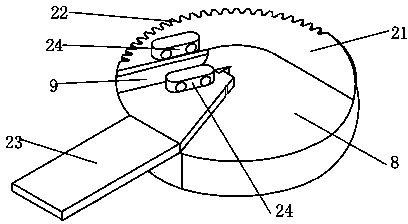
[0013] A kind of gear of workpiece rotation punching die, comprises wheel body 21, described wheel body 21 is provided with the workpiece groove 9 that places workpiece, one end of described workpiece groove 9 extends to the edge of wheel body 21, and the workpiece groove 9 The other end extends into the wheel body 21 and is connected with a fan-shaped groove 8, and the side of the wheel body 21 away from the fan-shaped groove 8 is provided with a rack and pinion 22, and the described wheel body 21 is located between the fan-shaped groove 8 and the workpiece groove 9 One side is provided with an outwardly extending stopper 23 .

[0014] In a preferred manner, splints 24 are provided on both sides of the workpiece groove 9 .

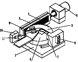
[0015] The present invention is the core part of the workpiece rotary stamping die, and the entire workpiece rotary stamping die includes a base 1, a gear 2 is hinged on the...


PUM


Abstract

The invention belongs to the technical field of metal processing tools and particularly relates to a gear of a workpiece rotating stamping die. The gear of the workpiece rotating stamping die comprises a gear body, wherein the gear body is provided with a workpiece groove for workpiece placement; one end of the workpiece groove extends to the edge of the gear body, and the other end of the workpiece groove extends into the gear body to be connected with a fan-shaped groove; one side of the gear body, which is far away from the fan-shaped groove, is provided with a gear rack, and one side of the gear body, which is positioned between the fan-shaped groove and the workpiece groove, is provided with a stopping workpiece extending to outside. In the invention, the mechanical processing of a tubular workpiece is realized, thereby increasing the efficiency and achieving the large-scale and industrialized production.

Description

technical field [0001] The invention belongs to the technical field of metal processing tools, and in particular relates to a gear for a rotary stamping die of a workpiece. Background technique [0002] In metal processing, especially when processing some small tubular parts, it is sometimes processed according to different workpiece requirements, such as processing one end of the tubular part into a hypotenuse or arc. The traditional processing method is manual operation. First fix the workpiece to be processed by hand or other equipment, and then use a cutting tool such as a cutting machine to cut the workpiece. There is this following defect in manual operation: the one, precision is not high. Manual operation has certain advantages for parts that do not require high precision. However, with the development of society, mechanical equipment is becoming more and more complex and sophisticated, and the precision requirements for the cooperation between each part are also ...

Claims


Application Information

Patent Timeline
Patent Type & Authority Patents(China)
IPC IPC(8): B21D9/05
Inventor 潘智平
Owner HUZHOU IRON FORCE METAL PROD
Why Eureka
Try Eureka