
Machining equipment for S-shaped curve bend

A processing equipment and curve technology, which is applied in the field of S-shaped curved pipe bending processing equipment, can solve the problems of high processing intensity, increase processing difficulty, and large workload, and achieve the effect of reducing processing difficulty, saving processing time, and high degree of automation.

Active Publication Date: 2017-09-01
芜湖德丰汽车零部件有限公司
View PDF8 Cites 0 Cited by
  • Summary
  • Abstract
  • Description
  • Claims
  • Application Information

AI Technical Summary

Problems solved by technology

However, this segmented processing method, due to the complicated trend of the S-shaped curved pipe during production, is prone to interference during segmental processing, which increases the difficulty of processing, and requires adjustment for each processing, which takes a long time. This method of processing requires many processes of manual participation, it is difficult to achieve mass production, and the workload is heavy and the processing intensity is high.

Method used


Image

  • Machining equipment for S-shaped curve bend
  • Machining equipment for S-shaped curve bend
  • Machining equipment for S-shaped curve bend

Examples


Embodiment Construction

[0017] In order to make the technical means, creative features, goals and effects achieved by the present invention easy to understand, the present invention will be further elaborated below.

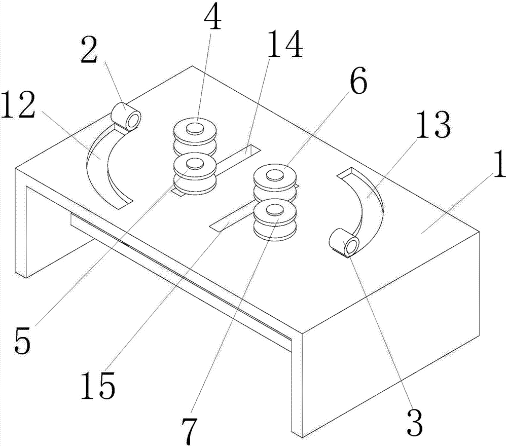
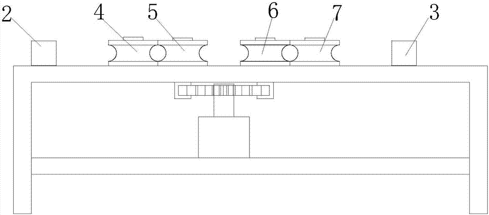
[0018] Such as Figure 1 to Figure 4 As shown, an S-curve pipe bending processing equipment includes a working platform 1, and the working platform 1 is provided with a No. 1 pipe sleeve 2 and a No. 2 pipe sleeve 3 distributed on the same straight line. The sleeve 2 is slidably installed on the left end of the working platform 1 counterclockwise, and the No. 2 pipe sleeve 3 is slidably installed on the right end of the working platform 1 counterclockwise. The connecting line between the No. 1 pipe sleeve 2 and the No. To the right, the No. 1 roller 4 located above the connecting line and fixed on the working platform 1, the first bending die 5 located below the connecting line and slidably installed on the working platform 1, and the first bending die 5 located above the connecting line...


PUM


Abstract

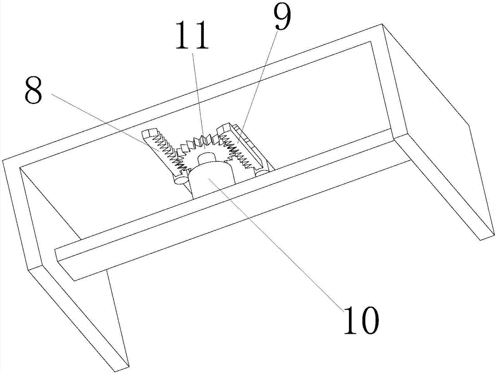
The invention relates to machining equipment for an S-shaped curve bend. The machining equipment comprises a working table, wherein a pipe sleeve I and a pipe sleeve II are arranged on the working table; the pipe sleeve I is mounted at the left end of the working table in an anticlockwise sliding manner; the pipe sleeve II is mounted at the right end of the working table in an anticlockwise sliding manner; a roller I, a first bending mold, a second bending mold and a roller II are distributed on a connecting line of the pipe sleeve I and the pipe sleeve II from left to right sequentially; a power system driving the first bending mold and the second bending mold to slide is connected with the first bending mold and the second bending mold and comprises a gear rack I connected with the first bending mold, a gear rack II connected with the second bending mold and a gear which is meshed with the gear rack I and the gear rack II and connected with a motor. The machining equipment for the S-shaped curve bend has the beneficial effects as follows: one-time machining molding of the S-shaped bend can be realized, interference in the bending process can be avoided, the machining difficulty is reduced, the machining time is saved, mechanical processing can be realized, the degree of automation is high, the production efficiency is improved, and large-scale production work can be performed.

Description

technical field [0001] The invention relates to the technical field of mechanical processing equipment, in particular to an S-curve pipe bending processing equipment. Background technique [0002] S-shaped curved pipes are sometimes encountered in factory production. During processing and production, the commonly used method is to bend through a pipe bending machine, continue to bend a steel pipe in sections, and process separately for final forming. However, this segmented processing method, due to the complicated trend of the S-shaped curved pipe during production, is prone to interference during segmental processing, which increases the difficulty of processing, and requires adjustment for each processing, which takes a long time. This method of processing requires many processes of manual participation, it is difficult to achieve mass production, and the workload is large and the processing intensity is high. Contents of the invention [0003] In order to avoid and so...

Claims


Application Information

Patent Timeline
Patent Type & Authority Applications(China)
IPC IPC(8): B21D11/07
CPCB21D11/07
Inventor 李红昌
Owner 芜湖德丰汽车零部件有限公司
Learn More