Spherical buoy and manufacturing method thereof

A manufacturing method and technology of buoys, which are applied to buoys, special-purpose ships, ships, etc., can solve the problems of increasing non-uniform impact of buoys, sinking of buoys, and reduction of carrying capacity, so as to optimize inner cavity space and function design, and simplify production process Requirements, the effect of reducing non-uniform impact

Inactive Publication Date: 2012-10-03
周涛
View PDF8 Cites 9 Cited by
  • Summary
  • Abstract
  • Description
  • Claims
  • Application Information

AI Technical Summary

Problems solved by technology

[0004] (1) Due to the existence of the flange and the anti-collision rubber ring, the smoothness of the surface of the spherical buoy is affected, and the non-uniform impact of waves on the buoy is increased, causing the buoy to roll and destroying the attitude stability of the buoy
The instability of buoy attitude will inevitably lead to the decrease of the accuracy of buoy attitude measurement and compensation, which will affect the measurement accuracy of marine instruments carried by buoys;
[0005] (2) The position of the flange is the part of the spherical buoy with the largest size, the most vulnerable to impact, and relatively weak mechanical strength. Under external impact, even with the protection of the anti-collision rubber ring, there is no guarantee that no deformation and cracks will occur. , prone to water leakage, resulting in damage to the carrying equipment, or even sinking the entire buoy;
[0006] (3) The production of spherical buoy shells requires high-precision molds, and the use of flanges and anti-collision rubber rings increases material consumption, resulting in higher production costs for buoys (this is especially important for consumable drifting buoys). Increased self-weight, decreased carrying capacity, etc.

Method used


Image

  • Spherical buoy and manufacturing method thereof
  • Spherical buoy and manufacturing method thereof
  • Spherical buoy and manufacturing method thereof

Examples


Embodiment 1

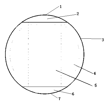
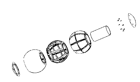
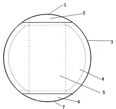
[0036] A GPRS communication module and a warning light are arranged in the first cavity of the spherical buoy, a six-axis acceleration sensor is arranged in the cavity of the spherical buoy body, a data acquisition module, a microprocessor and a battery are arranged in the second cavity, and the lower bottom cover is outside Set the rope pull ring to form an anchored wave buoy. The data acquisition module is a water pressure sensor, a direction sensor, etc. The data acquisition module sends the collected information to the microprocessor for processing and then sends it to the control platform through the GPRS communication module, which can be fixed. Real-time monitoring of marine dynamic environmental parameters such as ocean wave height, wave direction and wave period.

Embodiment 2

[0038] A Beidou (BD) antenna and warning light are installed in the first cavity of the spherical buoy, a six-axis acceleration sensor is installed in the cavity of the spherical buoy body, and a BD positioning communication host, data acquisition module, and microprocessor are installed in the second cavity. And the battery form a wave drifting buoy. The data collection module is a water pressure sensor, a direction sensor, etc., which can be drifted and moved to monitor the sea dynamic environment parameters such as wave height, wave direction, wave period, flow rate, and flow direction in real time.

Embodiment 3

[0040] The Beidou (BD) antenna and warning lights are installed in the first cavity of the spherical buoy, and the BD positioning communication host, signal acquisition and processing module and battery are installed in the cavity of the spherical buoy body and the second cavity to form a drifting buoy. Drifting and moving real-time monitoring of marine dynamic environmental parameters such as flow velocity and direction.


PUM


Abstract

The invention discloses a spherical buoy and a manufacturing method thereof. The spherical buoy comprises a spherical buoy body. The spherical buoy is characterized in that the periphery of the spherical buoy body is smooth, the spherical buoy body is provided with an upper top cover and a lower bottom cover, the upper top cover, the lower bottom cover and the spherical buoy body form three cavities from top to bottom, i.e. a first cavity, a spherical buoy body cavity and a second cavity, the spherical buoy body cavity is a cylindrical cavity, and a foam body is arranged at the periphery of the cylindrical cavity. The spherical buoy has the advantages of good gesture stability, simple structure and low cost.

Description

Technical field [0001] The invention belongs to the mechanical structure of a marine instrument, particularly a spherical buoy and a manufacturing method thereof. Background technique [0002] The spherical ocean buoy has been widely used as a platform for various marine environment detection instruments and has become one of the main tools for marine environment monitoring. [0003] The traditional spherical buoy structure is usually composed of two complete hemispherical butts. Some of the hemispherical structures are designed with a cover with a sealing ring for the convenience of equipment installation. Both hemispheres are designed with flanges (with sealing rings). The screws are fastened as a whole, and the flange is covered with a rubber ring to play the role of anti-collision buffer. This structure has the following problems: [0004] (1) Due to the existence of the flange and the anti-collision rubber ring, the smoothness of the spherical buoy's surface is affected, and t...

Claims


Application Information

Patent Timeline
Patent Type & Authority Applications(China)
IPC IPC(8): B63B22/24
Inventor 周涛
Owner 周涛
Why Eureka
Try Eureka