Directional yarn guide mechanism of computer flat knitting machine

A yarn guiding mechanism and technology of flat knitting machine, which are applied in the directions of knitting, weft knitting, textile and paper making, etc., can solve the problems of increasing the resistance of yarn traveling, unfavorable yarn guiding smoothly, and yarn breakage, etc., and achieve smooth guiding. Lead, good orientation effect

Active Publication Date: 2013-09-18
JIANGSU JINLONG TECHNOLOGY CO LTD
View PDF8 Cites 11 Cited by
  • Summary
  • Abstract
  • Description
  • Claims
  • Application Information

AI Technical Summary

Problems solved by technology

[0004] However, the above-mentioned CN102191618A has the following shortcomings: because the patent application scheme is proposed for different invention purposes, that is, it is not necessary to replace the spring when changing the yarn , so no technical inspiration is given on how to prevent the yarn located between the left and right clamping discs of the yarn clamping device from escaping from between the left and right clamping discs, more specifically, the actual use of the patent application scheme In the process, there is a problem that the yarn escapes from the gap between the left and right clamping discs of the yarn clamping device, that is, the problem that the yarn comes out of the clamping disc, and once the yarn escapes from the gap between the left and right clamping discs, the yarn feeding tension is out of control. Flaws appear in the fabric, and even normal weaving cannot be carried out
Furthermore, if in order to prevent the yarn from escaping from the left and right yarn clamping discs, the force of the spring is increased to realize the clamping force applied to the yarn by the spring to the yarn clamping discs, but there is a problem of taking care of one thing and losing another. This, that is, although it can prevent the yarn from escaping from between the left and right yarn discs, the so-called loss of the other will significantly increase the travel resistance of the yarn, which is not conducive to the smooth guidance of the yarn, and even cause yarn breakage.

Method used


Image

  • Directional yarn guide mechanism of computer flat knitting machine
  • Directional yarn guide mechanism of computer flat knitting machine

Examples


Embodiment

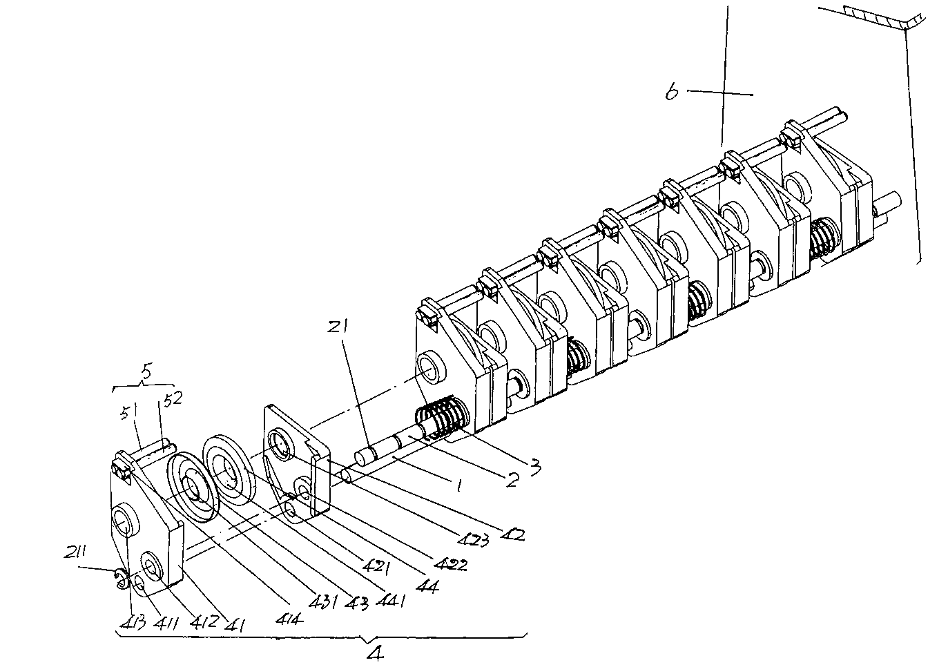
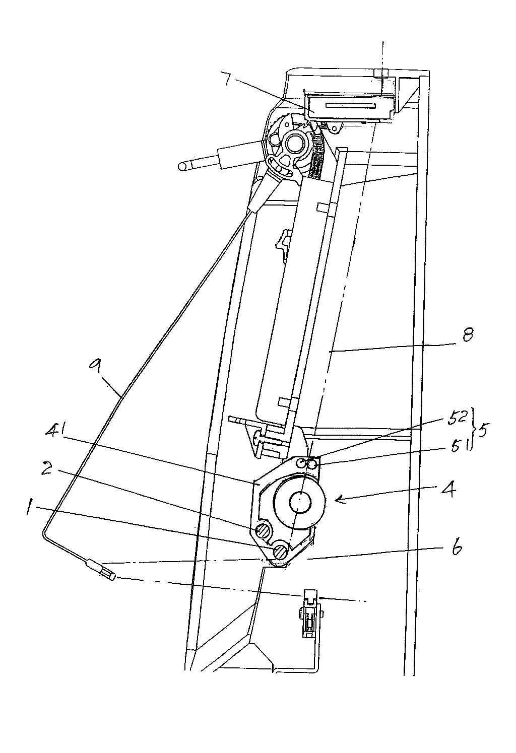
[0017] See figure 1 , a guide roller 1 and a spring bar 2 are given, the guide roller 1 and the spring bar 2 are obliquely parallel, and the guide roller 1 is located obliquely below the spring bar 2 in the state of use ( figure 2 Show). A set of limit snap ring grooves 21 are provided at intervals on the spring rod 2 , and a limit snap ring 211 is clamped in each limit snap ring groove 21 . There are two yarn clamping devices 4 in a group of yarn clamping devices 4 of the present invention corresponding to each two adjacent limit clips 211, and a chuck is allocated between every two adjacent yarn clamping devices 4 Seat spring 3 and two yarn guides 5.

[0018] The aforementioned chuck seat spring 3 is sleeved on the spring bar 2. In this embodiment, since the number of clamping devices 4 is eight, the number of chuck seat springs 3 is four, and the number of the yarn guide 5 is four. Quantity is equal to the quantity of clamping device 4 namely eight.

[0019] Sin...


PUM


Abstract

The invention provides a directional yarn guide mechanism of a computer flat knitting machine, which belongs to the technical field of auxiliary members of the computer flat knitting machine. The directed yarn guide mechanism comprises a yarn guide roller, a spring rod, a group of chuck seat springs and a group of yarn clamping devices, wherein the spring rod is parallel to the yarn guide roller; the group of chuck seat springs is sleeved on the spring rod; the group of yarn clamping devices is arranged on the yarn guide roller and the spring rod; and a yarn guider is arranged on each yarn clamping device and is correspondingly positioned above the yarn guide roller. The directional yarn guide mechanism has the advantages that acting force is provided for adjacent yarn clamping devices by the chuck seat springs arranged on the spring rod, so yarn passing through the yarn guiders is led out from the yarn guide roller under the clamping and the protection of the yarn clamping devices; since the yarn sequentially passes through the yarn guiders, the yarn clamping devices and the yarn guide roller, a good directional effect is achieved, the condition that the yarn escapes from the yarn clamping devices cannot occur and the yarn can be smoothly guided to a knitting mechanism.

Description

technical field [0001] The invention belongs to the technical field of auxiliary components of a computerized flat knitting machine, and in particular relates to a directional yarn guide mechanism of a computerized flat knitting machine . Background technique [0002] As known in the industry, the computerized flat knitting machine is equipped with a yarn guide mechanism, which includes a plurality of left and right clamping disks configured in pairs and the number is the same as the number of yarns used by the knitting mechanism. Equal yarn clamping device, the yarn drawn from the yarn feeder or directly from the yarn disc is adjusted to a suitable clamping force by the yarn clamping device, and then guided to the knitting yarn through the yarn guide ring on the yarn guide rod of the pretension adjustment mechanism. Body weave. [0003] The industry customarily refers to the yarn guiding mechanism as a yarn clamping mechanism, and the 0003-0004 paragraph of the descri...

Claims


Application Information

Patent Timeline
Patent Type & Authority Patents(China)
IPC IPC(8): D04B15/56
Inventor 金永良孙健兰先川
Owner JIANGSU JINLONG TECHNOLOGY CO LTD
Why Eureka
Try Eureka