Method and apparatus for synchronizing corresponding landmarks among a plurality of images

a landmark and image technology, applied in image analysis, image enhancement, instruments, etc., can solve the problems of not all forms of cancerous growths are easily detected, abnormal cells cannot be controlled, and defects may be detected in objects, so as to reduce the interpretation time of ctc cases, increase the detection rate of potentially cancerous polyps, and navigate smoothly

Active Publication Date: 2012-04-17
SONY CORP +1
View PDF51 Cites 4 Cited by
  • Summary
  • Abstract
  • Description
  • Claims
  • Application Information

AI Technical Summary

Benefits of technology

[0019]In one aspect, a method is provided for synchronizing corresponding landmarks among a plurality of images of an elastic object. The method includes identifying a plurality of landmarks in a first image of the object and a second image of the object, determining a correspondence between the landmarks in the first image and the landmarks in the second image, determining a distance transformation between a pair of adjacent landmarks in the first image and the corresponding pair of adjacent landmarks in the second image, and when displaying the first and second images, using the distance transformation to smoothly navigate between the adjacent landmarks such that corresponding landmarks of the first and second images are arrived at about simultaneously during navigation.
[0021]In another aspect, a computer readable medium is provided for use by an image processing system. The medium includes instructions directing the system to identify a plurality of landmarks in a first image of the object and a second image of the object, instructions directing the system to determine a correspondence between the landmarks in the first image and the landmarks in the second image, instructions directing the system to determine a distance transformation between a pair of adjacent landmarks in the first image and the corresponding pair of adjacent landmarks in the second image, and instructions directing the system, using the distance transformation, to enable a user, when viewing the first and second images using the system, to smoothly navigate between the adjacent landmarks such that corresponding landmarks of the first and second images are arrived at about simultaneously during navigation.

Problems solved by technology

For instance, internal defects in an object may be detected.
Although there are many different kinds of cancer, they all share a common cause: an uncontrollable growth of abnormal cells.
However, not all forms of cancerous growths are easily detected using tomographic reconstruction.
Colonic polyps develop slowly and may take years before becoming cancerous.
So few individuals are screened because people typically find the screening methods for colon cancer distasteful.
Due to the time consuming and invasive nature of a colonoscopy, many people choose not to have the colonoscopy.
However, currently CTC is not a practical clinical tool for colon cancer screening.
Currently, however, interpretation of an entire CTC examination is time consuming.
In addition, the diagnostic performance of CTC currently remains vulnerable to perceptual errors.
A low detection rate may result from the system and method used to display and view the images.
Unlinked images may create difficulty for a user when determining whether or not corresponding locations in the prone and supine image sets are being viewed.
Guessing whether the portion of the colon being viewed in the prone image set is the same portion of the colon being viewed in the supine image set is very time consuming due to the manual, imprecise nature of the analysis.
Forcing a user to guess at colon location accounts for an extremely long CTC case interpretation time per patient.
Even if a user thinks the user is viewing two corresponding locations of a colon, currently the user may not be certain.
Also, rough estimation of corresponding locations provides for a highly inaccurate procedure for distinguishing excess material from potential cancerous growths or other objects.
The low detection rate of detecting polyps using a CTC examination mentioned above is partially caused by a user's inability to determine whether the user is viewing corresponding locations of the colon in prone and supine views.

Method used


Image

  • Method and apparatus for synchronizing corresponding landmarks among a plurality of images
  • Method and apparatus for synchronizing corresponding landmarks among a plurality of images
  • Method and apparatus for synchronizing corresponding landmarks among a plurality of images

Examples


Embodiment Construction

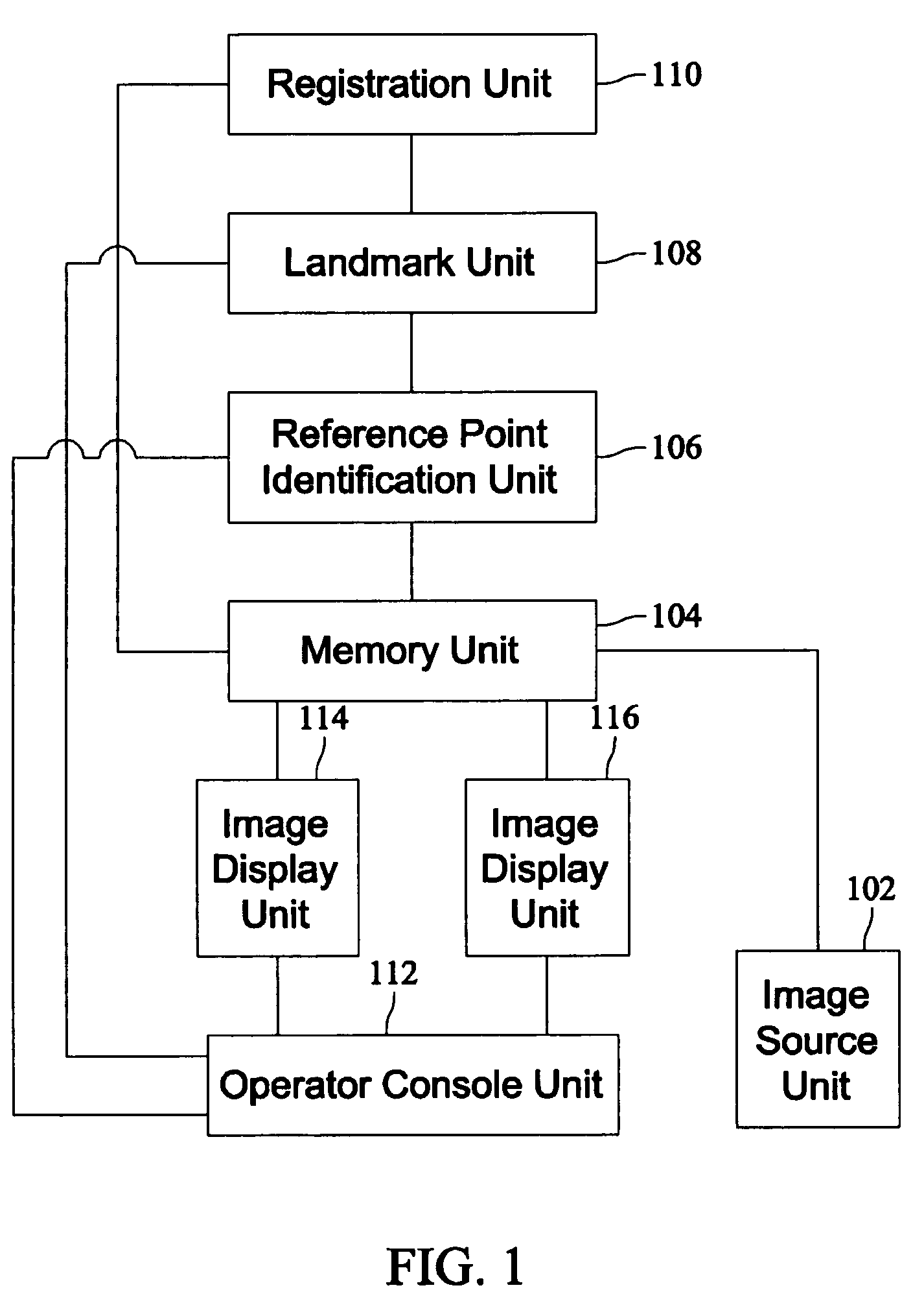
[0026]FIG. 1 is a schematic block diagram of an image processing system 100 in accordance with an embodiment of the present invention. The system 100 includes an image source unit 102. The image source unit 102 contains a first image set 103 and a second image set 105 (not shown) of an object, such as, but not limited to, an elastic object. The system 100 also contains a memory unit 104, a reference point identification unit 106, a landmark unit 108, a registration unit 110, an operator console 112, an image display unit 114, and an image display unit 116.

[0027]In an embodiment, the system 100 preprocesses image data 103, 105 and then makes the processed image data 103, 105 available for display and navigation by a user. Additionally or alternatively, the image data 103, 105 is available for display prior to being processed by the system 100. The image source unit 102 provides the image data 103, 105 for processing to the memory unit 104. The memory unit 104 stores the image data 10...


PUM


Abstract

A method is provided for synchronizing corresponding landmarks among a plurality of images of an elastic object. The method includes identifying a plurality of landmarks in a first image of the object and a second image of the object, determining a correspondence between the landmarks in the first image and the landmarks in the second image, determining a distance transformation between a pair of adjacent landmarks in the first image and the corresponding pair of adjacent landmarks in the second image, and when displaying the first and second images, using the distance transformation to smoothly navigate between the adjacent landmarks such that corresponding landmarks of the first and second images are arrived at about simultaneously during navigation.

Description

BACKGROUND OF THE INVENTION[0001]The present invention generally relates to a system and method for image processing of multiple images of an object. In particular, the present invention relates to a system and method for synchronizing corresponding landmarks among multiple images of an object.[0002]Medical diagnostic imaging systems encompass a variety of imaging modalities, such as x-ray systems, computerized tomography (CT) systems, ultrasound systems, electron beam tomography (EBT) systems, magnetic resonance (MR) systems, and the like. Medical diagnostic imaging systems generate images of an object, such as a patient, for example, through exposure to an energy source, such as x-rays passing through a patient, for example. The generated images may be used for many purposes. For instance, internal defects in an object may be detected. Additionally, changes in internal structure or alignment may be determined. Fluid flow within an object may also be represented. Furthermore, the i...

Claims


Application Information

Patent Timeline
Patent Type & Authority Patents(United States)
IPC IPC(8): G06K9/32G06K9/00G06K9/62G06K9/18G06V30/224
CPCG06K9/6206G06T7/0028G06T7/0038G06T19/003G06T2207/10081G06T2207/30032G06T2219/028G06T2219/2004G06T7/33G06T7/38G06V10/754
Inventor SIROHEY, SAAD AHMEDCAPOLUNGHI, RENAUDAVINASH, GOPAL B.LAUNAY, LAURENTKNOPLIOCH, JEROME FRANCOIS
Owner SONY CORP
Why Eureka
Try Eureka