AI technical title is built by Patsnap AI team. It summarizes the technical point description of the patent document.
A technology of laser measurement and sheet metal, which is applied in the direction of measuring devices, optical devices, instruments, etc., can solve the problems of continuous measurement of sheet thickness and achieve the effect of easy synchronization
Active Publication Date: 2012-10-03
HARBIN INST OF TECH
View PDF3 Cites 59 Cited by
Summary
Abstract
Description
Claims
Application Information
AI Technical Summary
This helps you quickly interpret patents by identifying the three key elements:
Problems solved by technology
Method used
Benefits of technology
Problems solved by technology
[0004] The purpose of the present invention is to provide a laser measuring device for the thickness of the plate to solve the problem that the existing laser thickness measurement method cannot realize continuous measurement of the thickness of the plate
Method used
Image
Click on the blue label to locate the original text in one second.
Reading with bidirectional positioning of images and text.
Examples
specific Embodiment approach 1
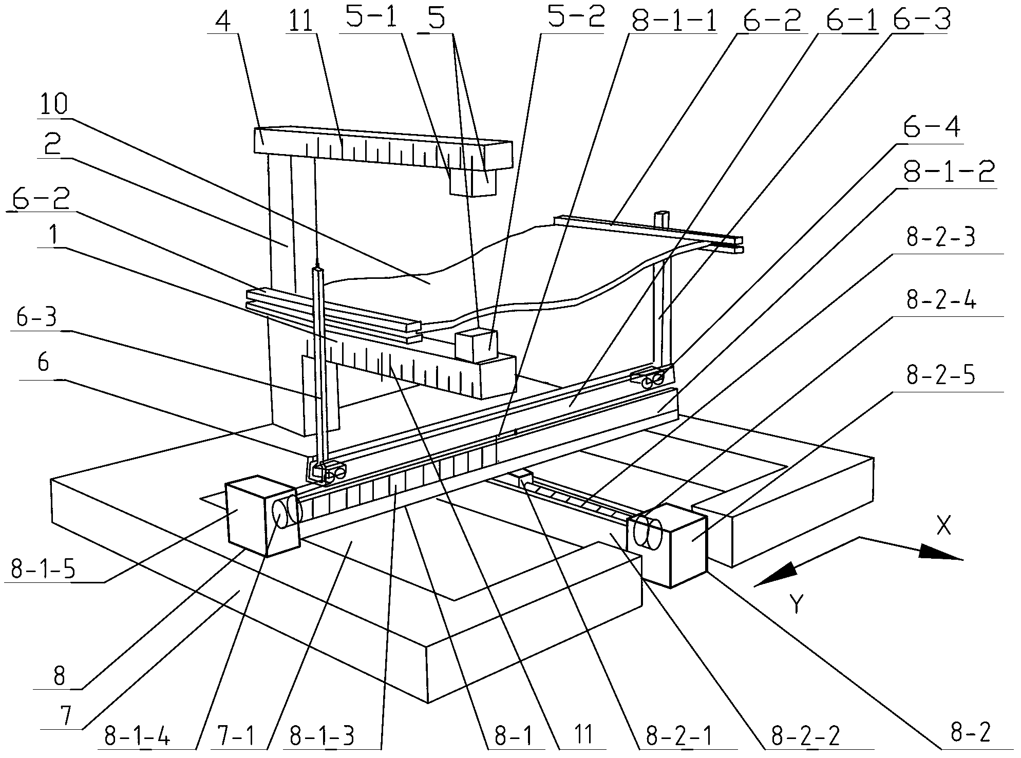
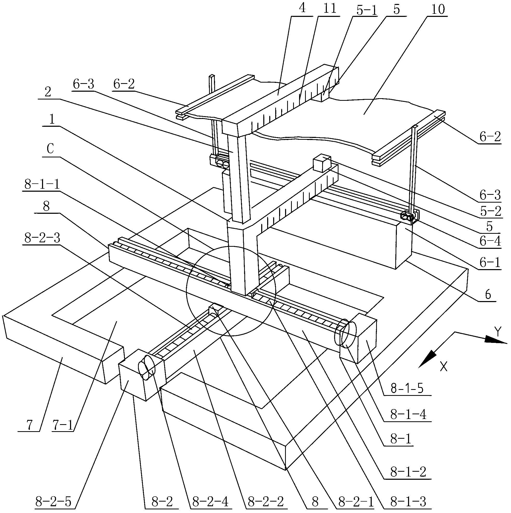
[0015] Specific implementation mode one: combine figure 1 , figure 2 and Figure 4 to Figure 10 Explain, the laser measuring device for plate thickness in this embodiment, the laser measuring device includes a lower arm 1, a side arm 2, a fine-tuning device 3, an upper arm 4, a fixed platform 6, a working table 7, two laser displacement sensors 5, Two motion platforms 8 and four limit mechanisms 9; the fine-tuning device 3 includes a drive motor 3-1, a transmission mechanism 3-2, a gear 3-3, a wheel shaft 3-4 and a U-shaped slide rail 3-5, and a fixed platform 6 Including guide track 6-1, two long-arm clamps 6-2, two supports 6-3 and two sets of rollers 6-4, two moving platforms 8 are upper moving platform 8-1 and lower moving platform 8- 2. The two laser displacement sensors 5 are respectively an upper laser displacement sensor 5-1 and a lower laser displacement sensor 5-2;
[0016]The upper arm 4 and the lower arm 1 are arranged parallel and side by side up and down, the...
specific Embodiment approach 2
[0019] Specific implementation mode two: combination figure 1 Explain that the upper motion platform 8-1 described in this embodiment includes an upper mounting base 8-1-1, an upper bracket 8-1-2, an upper ball screw 8-1-3, and an upper coupling 8-1-4 And the upper stepper motor 8-1-5;
[0020] The upper mounting base 8-1-1 is arranged on the upper bracket 8-1-2, the upper mounting base 8-1-1 is connected with the upper ball screw 8-1-3, and the rotating shaft of the upper stepping motor 8-1-5 Connect with the upper ball screw 8-1-3 through the upper coupling 8-1-4, driven by the upper stepper motor 8-1-5, the upper mounting base 8-1-1 is on the upper bracket 8-1-2 Sliding, the lower motion platform 8-2 includes the lower mounting base 8-2-1, the lower bracket 8-2-2, the lower ball screw 8-2-3, the lower coupling 8-2-4 and the lower stepping motor 8 -2-5, the upper bracket 8-1-2 is fixed on the lower mounting base 8-2-1, and the lower mounting base 8-2-1 is arranged on the l...
specific Embodiment approach 3
[0021] Specific implementation mode three: combination figure 1 Note that the upper arm 4 and the lower arm 1 of this embodiment are respectively provided with scale marks 11 along their respective length directions (accurate positioning of the laser displacement sensor 5 can be realized). Others are the same as in the first or second embodiment.
PUM
Abstract
The invention discloses a lasermeasurement device for the thickness of a plate, and relates to a lasermeasurement device. In order to the solve the problems that as for a conventional laser measurement method, continuous measurement for the thickness of the plate can not be carried out, the technical scheme I is adopted as follows: an upper arm and a lower arm are arranged in parallel; the upper arm is connected with a side arm; the lower arm is connected with a lateral wall of a U-shaped slide rail; the side arm is connected with chutes in a sliding manner; a horizontal gear on the side arm is meshed with a gear wheel; an upper and a lower laser displacement sensors are respectively fixed on the upper and the lower arms; a long-arm clamp is fixed on a support which is fixed on one group of rollers; two groups of rollers roll along a guidance groove of a guidance rail; each group of rollers are limited through two limiting mechanisms; the side wall is fixed on a working table; the guidance rail is fixed on an upper installation base of an upper motion platform; an upper bracket of the upper motion platform is fixed on a lower installation base of a lower motion platform; and the lower motion platform is arranged in the working table. The technical scheme II is different from the technical scheme I, the side wall is fixed on the upper installation base of the upper motion platform. Due to the adoption of the device provided by the invention, continuous measurement for the thickness of the plate can be carried out.
Description
technical field [0001] The invention relates to a laser measuring device, in particular to a laser measuring device for plate thickness. Background technique [0002] In the industrial production process, the thickness uniformity of the plate is a key factor affecting the later forming, and it is one of the important signs to measure whether the plate is qualified or not. Quickly and effectively measure the plate thickness distribution in the plane of the plate before forming, which can provide a basis for the analysis of the later forming effect. In high-precision fields such as aviation, aerospace, and deep-sea exploration, the requirements for plate thickness distribution before forming plate parts are more stringent. [0003] There are two main types of existing thickness measurement methods, one is contact thickness measurement methods, such as micrometer and ultrasonic thickness measurement, the measurement points need to be marked before measurement, and manual measu...
Claims
Application Information
Patent Timeline
Application Date:The date an application was filed.
Publication Date:The date a patent or application was officially published.
First Publication Date:The earliest publication date of a patent with the same application number.
Issue Date:Publication date of the patent grant document.
PCT Entry Date:The Entry date of PCT National Phase.
Estimated Expiry Date:The statutory expiry date of a patent right according to the Patent Law, and it is the longest term of protection that the patent right can achieve without the termination of the patent right due to other reasons(Term extension factor has been taken into account ).
Invalid Date:Actual expiry date is based on effective date or publication date of legal transaction data of invalid patent.

