Upper table top moving device for microscope

A mobile device and microscope technology, which is applied in the direction of microscopes, transmission devices, friction transmission devices, etc., can solve the problems of heavy, unsmooth, large impact, etc., and achieve the effects of shock absorption, convenient manufacturing, installation and maintenance, and simple structure

Inactive Publication Date: 2012-10-03
NANTONG JIANGZHONG PHOTOELECTRIC
View PDF1 Cites 0 Cited by
  • Summary
  • Abstract
  • Description
  • Claims
  • Application Information

AI Technical Summary

Problems solved by technology

[0002] The table moving device of the microscope is mainly used for the lateral movement between the upper table and the lower table of the microscope. The existing technology adopts gear transmission. Due to the meshing transmission between the gears, there is a gap between the teeth during the transmission process, and the impact force bigger
In addition, when turning the handwheel, it is relatively heavy and not smooth, and the movement has a certain range

Method used


Image

  • Upper table top moving device for microscope

Examples


Embodiment Construction

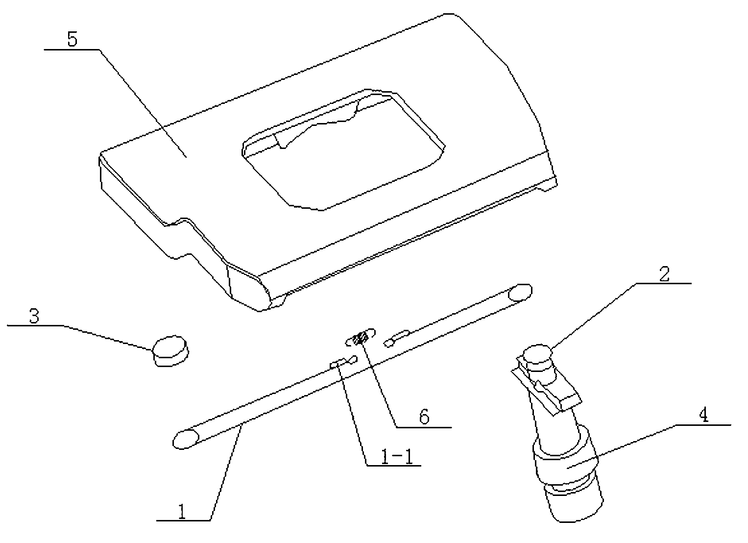
[0009] refer to figure 1 , the specific embodiment adopts the following technical solutions: a microscope table top moving device, which includes a steel wire rope 1, the first pulley 2, the second pulley 3 and the handwheel assembly shaft 4, the first pulley 2 and the handwheel assembly The shaft 4 is connected, the second pulley 3 is fixedly connected with the upper table 5, and the first pulley 2 and the second pulley 3 are connected by a wire rope 1, and the wire rope 1 is connected between the first pulley 2 and the second pulley 2 At least two turns are wound up, and the two ends of the steel wire rope 1 are connected by a tension spring 6 .

[0010] The steel wire rope 1 winds two to four times on the first pulley 2 and the second pulley 3, which not only increases the contact area between the steel wire rope and the pulley, but also reduces the final force of each steel wire rope to avoid sliding between the steel wire rope and the pulley , Produce finale force on the...


PUM


Abstract

The invention discloses an upper table top moving device for a microscope, relating to the technical field of microscope parts. The upper table top moving device for the microscope comprises a steel wire rope, a first pulley, a second pulley and a hand wheel assembly shaft, wherein the first pulley is connected with the hand wheel assembly shaft, the second pulley is fixedly connected with an upper table top, the first pulley is connected with the second pulley through the steel wire rope, at least two rings of the steel wire rope are wound on the first pulley and the second pulley, and two ends of the steel wire rope are connected through a tension spring. By adopting the steel wire rope gearing, the upper table top moving device has the advantages of simple structure, convenience for manufacture and installation and maintenance, capability of absorbing shaking, and stability in transmission.

Description

technical field [0001] The invention relates to the technical field of microscope accessories, in particular to a microscope upper table moving device. Background technique [0002] The table moving device of the microscope is mainly used for the lateral movement between the upper table and the lower table of the microscope. The existing technology adopts gear transmission. Due to the meshing transmission between the gears, there is a gap between the teeth during the transmission process, and the impact force larger. In addition, when turning the handwheel, it is relatively heavy and not smooth, and the movement has a certain range. Contents of the invention [0003] The object of the present invention is to provide a moving device for the upper stage of the microscope, which is driven by a wire rope, has a simple structure, is convenient to manufacture, install and maintain, can absorb vibrations, and has stable transmission. [0004] In order to solve the existing prob...

Claims


Application Information

Patent Timeline
Patent Type & Authority Applications(China)
IPC IPC(8): G02B21/26F16H19/06
Inventor 许应龙郭垂宏许秀南刘敏
Owner NANTONG JIANGZHONG PHOTOELECTRIC
Why Eureka
Try Eureka