

Rooftop linkage tracing photovoltaic stent and photovoltaic power generation system
A photovoltaic bracket and transmission chain technology, applied in photovoltaic power generation, photovoltaic module support structure, photovoltaic module, etc., can solve the problems of large wind resistance and low power of photovoltaic power generation system, and achieve light weight, high overall structural strength and lower requirements Effect
- Summary
- Abstract
- Description
- Claims
- Application Information
AI Technical Summary
Problems solved by technology
Method used
Image

Examples
Embodiment 1
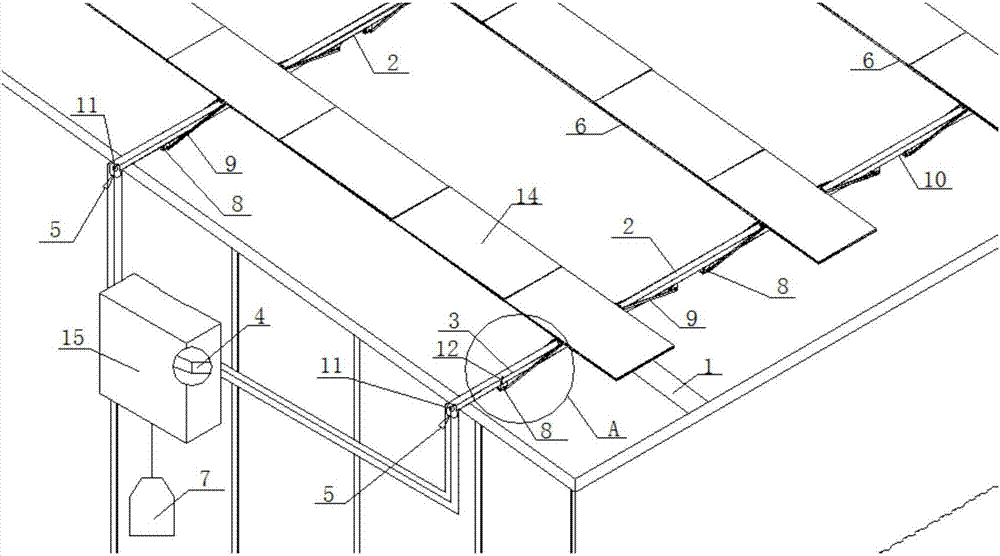
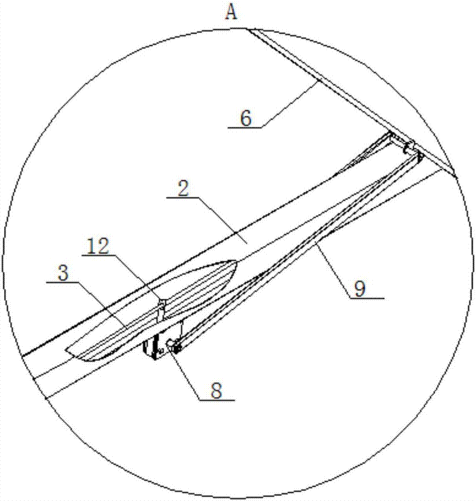
[0041] Such as figure 1 Shown is an example of a linkage tracking photovoltaic support installed on a color steel tile roof. The color steel tile here is made of color-coated steel plate, which is rolled and cold-formed into various wave-shaped profiled plates. It is suitable for industrial and civil buildings, warehouses, special buildings, and the roof of large-span steel structure houses. Currently, it is commonly used Color steel tiles have angle-relaxed color steel tiles, 180-degree occlusal color steel tiles, and 360-degree occlusal color steel tiles. The roof bearing capacity of this structure is limited, but the use area of color steel tiles is large, and the roof cannot be effectively utilized. , while the quality of the photovoltaic brackets in the prior art is relatively large, and a large number of load bearing calculations are required. Even if some structural adjustments are made on the color steel tile roof, its bearing capacity is still unable to install the ...
Embodiment 2
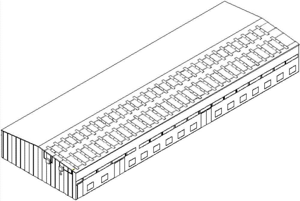
[0054] Such as Figure 4 Shown is a structural schematic diagram of the linkage tracking type photovoltaic support on the roof of a high-rise building according to the present invention. The roofs of high-rise buildings here are made of poured concrete, and a waterproof layer is laid on the roof. Generally, a single roof is small in length and narrow in width, resulting in a small area. In addition, the roofs of high-rise buildings are uneven in height. Therefore, it is necessary to Utilizing the roofs of high-rise buildings, or avoiding the adverse effects caused by uneven heights, this is a technical problem that cannot be solved by the currently disclosed linkage tracking photovoltaic brackets.
[0055] The technical measure of present embodiment is, make full use of the parapet wall of building to make windproof barrier, and whole photovoltaic support is lower than the height of parapet wall, and triangular support frame 13 is shelved on the waterproof layer, according to ...
PUM
 Abstract
Description
Claims
Application Information