Stamping punch

A technology of punching head and punching surface, which is applied in the field of stamping dies, which can solve the problems of high impact force, increased production cost, and damage to the punch, and achieve the effects of relieving the impact force, reducing production cost, and avoiding damage

Inactive Publication Date: 2012-10-10
TIANJIN HUASHUN AUTO PARTS MFR GRP
View PDF0 Cites 3 Cited by
  • Summary
  • Abstract
  • Description
  • Claims
  • Application Information

AI Technical Summary

Problems solved by technology

[0002] The processing of metal parts is usually completed by stamping dies. Because the impact force is very large during stamping, it is easy to cause damage to the punch.
The punches are all made of precious metal alloys, and frequent replacement of new punches increases the production cost

Method used


Image

  • Stamping punch

Examples


Embodiment Construction

[0009] The present invention will be further described below by embodiment.

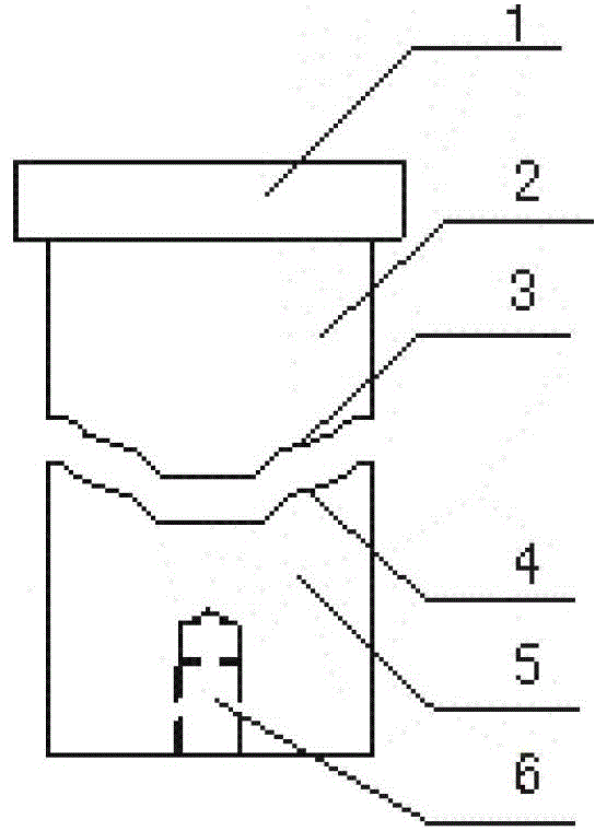
[0010] attached by figure 1 It can be seen that the present invention is composed of an upper punch 2 and a lower punch 5, the upper end of the upper punch 2 is provided with a clamping platform 1, the bottom of the lower punch 5 is provided with a connecting screw hole 6, and the upper punch 2 is provided with a connecting screw hole 6. 2 The bottom and the upper part of the lower punch 5 are provided with an upper punch surface 3 and a lower punch surface 4 that cooperate with each other.

[0011] It should be noted that the embodiments described in the present invention are only preferred ways to realize the present invention, and changes that are only obvious and belong to the overall concept of the present invention shall fall within the protection scope of the present invention.


PUM


Abstract

A stamping punch is used for stamping a mold. The stamping punch comprises an upper punch and a lower punch, a clamp platform is arranged at the upper end part of the upper punch, a connection thread hole is formed at the bottom of the lower punch, and an upper punch face and a lower punch face which are matched with each other are arranged at the bottom of the upper punch and the upper part of the lower punch respectively. The beneficial effects are as follows: the two-segment type punch is adopted to effectively alleviate the stamping force applied on the punch, avoid damaging the punch and also reduce the product cost at the same time.

Description

technical field [0001] The invention relates to a stamping die, in particular to a punch of the stamping die. Background technique [0002] The processing of metal parts is usually completed by stamping dies. Because the impact force is very large during stamping, it is easy to cause damage to the punch. The punches are all made of precious metal alloys, and frequent replacement of new punches increases the production cost. Contents of the invention [0003] In order to solve the above problems, the present invention provides a stamping punch, which can reduce the impact force during depressurization, and avoid damage to the punch due to excessive impact force. [0004] In order to achieve the above object, the technical scheme adopted in the present invention is: [0005] A stamping punch, characterized in that: it consists of an upper punch and a lower punch, the upper end of the upper punch is provided with a clamping platform, the bottom of the lower punch is provide...

Claims


Application Information

Patent Timeline
IPC IPC(8): B21D37/00
Inventor 刘勇刘兴全郭旭光
Owner TIANJIN HUASHUN AUTO PARTS MFR GRP
Why Eureka
Try Eureka