
Super capacitor and capacitance compensation circuit structure capable of eliminating low-order harmonic

A supercapacitor and circuit structure technology, applied in the field of circuits, can solve problems such as supercapacitors have little influence on capacitors and large currents

Active Publication Date: 2012-10-10
SHANGHAI NAJIE COMPLETE SETAB OF ELECTRIC
View PDF5 Cites 0 Cited by
  • Summary
  • Abstract
  • Description
  • Claims
  • Application Information

AI Technical Summary

Problems solved by technology

[0004] The purpose of the present invention is to provide a supercapacitor and eliminate low-order harmonic capacitor compensation circuit structure, use the supercapacitor voltage mutation at both ends of the supercapacitor to have little effect on the supercapacitor to solve the problem of large current when the capacitor is connected to compensation, and use the supercapacitor Limit the voltage rise speed at both ends of the capacitor, and reduce the damage to the capacitor caused by the large current at the moment of capacitor compensation

Method used

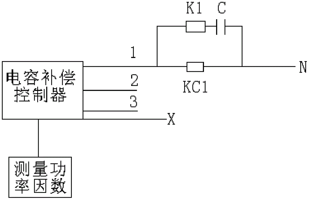

Image

  • Super capacitor and capacitance compensation circuit structure capable of eliminating low-order harmonic
  • Super capacitor and capacitance compensation circuit structure capable of eliminating low-order harmonic
  • Super capacitor and capacitance compensation circuit structure capable of eliminating low-order harmonic

Examples


Embodiment 1

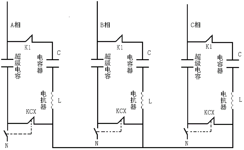
[0015] Such as figure 2 As shown, in one embodiment of the present invention, the circuit structure includes a three-phase power supply, the normally open contact of the supercapacitor and the contactor KCX is connected to the N line on the A phase, and the A phase is connected to the first The normally open contact of the group contactor K1 is connected from the other end of the contactor contact K1 to the compensation capacitor C, from the other end of the compensation capacitor C to one end of the reactor L, and from the other end of the reactor L to the contactor KCX One end of the normally closed contact is connected to the terminal of the normally closed contact reactor L of phase B at the same time, and the other end of the normally closed contact of the contactor KCX is connected to the connection between the normally open contact of the contactor and the super capacitor; , The connection method on phase C is the same as that on phase A; the leads below the three-phas...

Embodiment 2

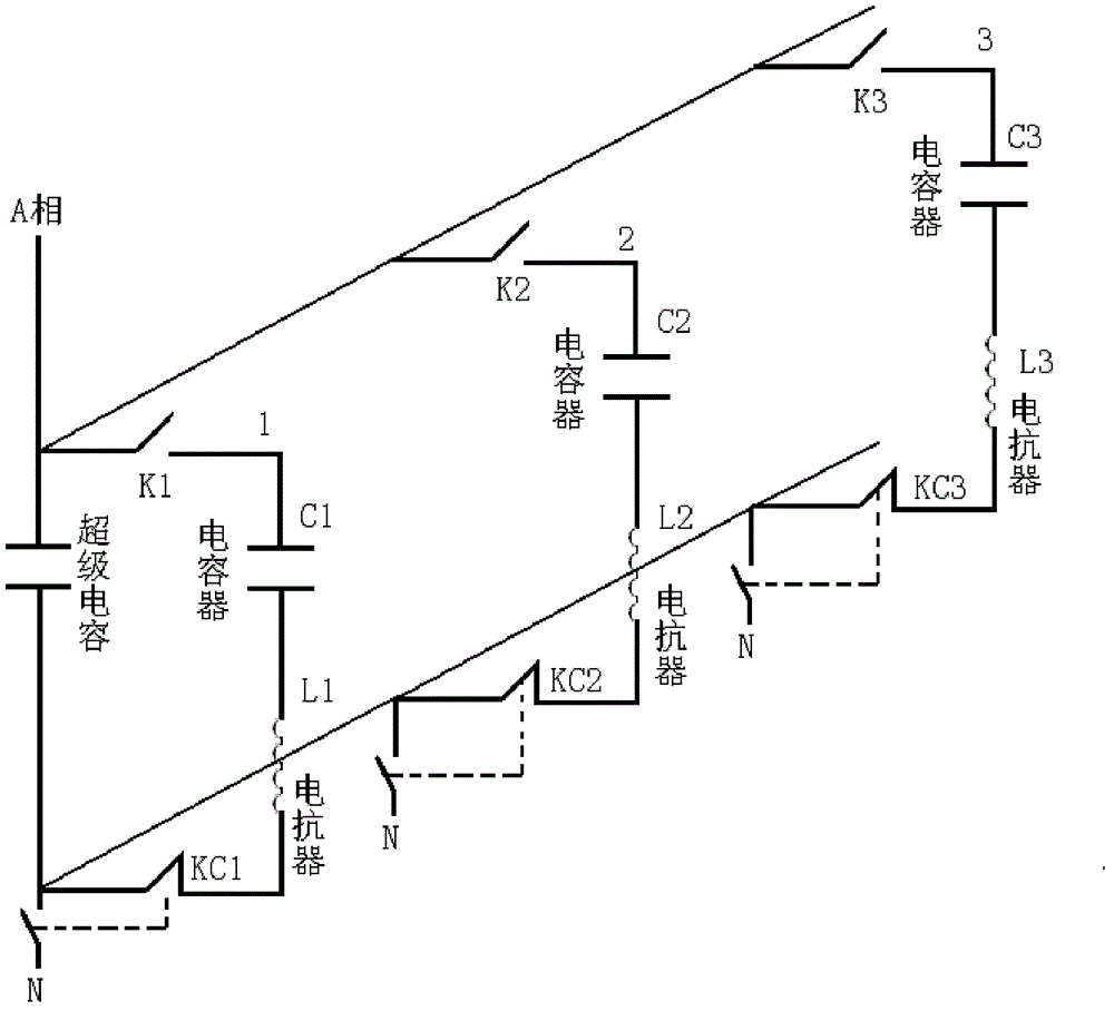
[0017] Such as image 3 As shown, in another embodiment of the present invention, the circuit structure includes a phase power supply, one end of the normally open contact of the A-phase contactor K1 is connected, and at the same time is connected to one end of the supercapacitor, and the other end of the supercapacitor is connected to the contactor KC1 One end of the normally open contact is connected, and the other end of the normally open contact of the contactor KC1 is connected to the N line; the other end of the normally open contact of the contactor K1 is connected to the compensation capacitor C1, and the other end of the compensation capacitor C1 is connected to the reactance L1, and the reactance L1 is another One end is connected to the normally closed contact of contactor KC1, and the normally closed contact of contactor KCX is connected to the supercapacitor and the normally open connection of contactor KC1; the second group of compensation capacitors is connected ...


PUM


Abstract

The invention discloses a super capacitor and a capacitance compensation circuit structure capable of eliminating a low-order harmonic. The super capacitor and the structure are characterized in that: a capacitor group, a harmonic elimination reactor and the super capacitor are comprised; the capacitor group and the harmonic elimination reactor are connected in series so as to form a branch; the super capacitor is connected in parallel with the branch. According to the invention, a problem that a large current generates when capacitors are accessed for compensation can be solved through the principle that abrupt voltage change of the two ends of the super capacitor has little influence on the super capacitor. The super capacitor restricts a rate of voltage rise of the two ends of the capacitor so that damage generated by the large current at a capacitor compensation moment to the capacitor can be reduced.

Description

technical field [0001] The invention relates to the field of circuits, in particular to a supercapacitor and a compensation circuit structure for eliminating low-order harmonic capacitance. Background technique [0002] In the power supply system, due to the loss on the line after the electric energy is transmitted to the user end, the terminal voltage decreases and the power factor decreases. In order to increase the voltage at the user end, the power factor must be improved to reduce the loss on the line. The most used method to improve power factor in power distribution system is to use capacitor bank compensation to improve power factor. In the circuit using capacitor bank as compensation method, due to the characteristics of the capacitor itself, the voltage across the capacitor cannot change abruptly, that is, it can only rise slowly or drop slowly. Rapidly changing voltages across capacitors will reduce the life of the capacitor bank. [0003] To sum up, in view of...

Claims


Application Information

Patent Timeline
Patent Type & Authority Applications(China)
IPC IPC(8): H02J3/01H02J3/18
CPCY02E40/30Y02E40/40
Inventor 张超沈剑鸣
Owner SHANGHAI NAJIE COMPLETE SETAB OF ELECTRIC
Learn More